I am currently working on a project based off of https://www.instructables.com/Arduino-Vocal-Effects-Box/ where I adjust it for a guitar. I have used Arduino a couple of times and have a decent basic understanding of circuits and coding knowledge, but I am by no means experienced.
I would like to fully understand each part of the circuit and then be able to develop it further, so I am recreating a similar circuit but not just copying the schematic from the provided link. From the point where I can show the input is working I will expand the complexity of the design.
As of this layout, the voltage output is giving 0v no matter if the strings are played or not. I also tried a circuit with a very similar layout and a constant DC input instead of the guitar. It was giving an output proportional to DC that I input but somehow the gain was less than 1 despite the amp being used in non-inverting configuration.
I am currently just looking to get some sort of feasible output by adding gain to the signal in order to be able to process it on Arduino. I will add a voltage divider to offset, as well as filtering later in the project. Right now I would like to be able to at least show the voltage input to the arduino is affected by playing the guitar, whether or not it produces the desired output.
On the breadboard, the left - rail is gnd, left + rail is 5V (currently unused but will be used for voltage offset), right - rail is -9V and the right + rail is +9V. The right rails are Vcc+ and Vcc- where two 9V batteries are arranged as shown in the schematic to reach these points.
Since the Arduino can be damaged by voltages greater than 5V or negative voltages, it's slightly dangerous to connect an op-amp with +/-9V supplies.
r
You can add a Over Voltage Protection Circuit between the op-amp and the Arduino. [LINK CORRECTED]
The amplifier schematic looks OK. (I'm not going to try-to figure-out the photo. )
If you're getting 0VDC out of the op-amp with no signal is a clue that it's probably working.
You should have a resistor (about 1M) between the + input and ground to keep it from "floating" when the guitar is not connected.
Or if you apply 5V to the "guitar input" it should saturate at -9V. (Disconnect it from the Arduino first!)
You should get a "usable signal" without amplification and just a bias circuit. Here is a bias circuit, but change the resistors to 1M for a guitar, and you can use a 0.1uF cap.
Thanks for the help. With that bias circuit does it have to be an electrolytic capacitor? I'm going to assume that the 1M resistors are to prevent the current from the line in going to either pos or gnd? I don't fully understand the relevance as to why a higher resistance is required as long as they are identical.
Also for the protection circuit that you recommended, would I have to create the circuit for each of the + and - VCC rails with separate pots?
I'm just measuring voltages by connecting whichever point I'd like to measure to the analog in. Also, don't blame you for staying away from the photo of the breadboard lol
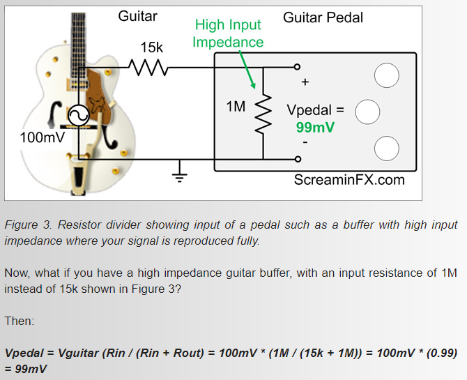
Because guitars have passive transducers and circuits that can not operate into relatively low impedance loads. A typical guitar amplifier has a 1M input, the unmodified input impedance of the line level input shown above is 5,000 ohms.
You could likely eliminate the entire op amp circuit by increasing the ADC sensitivity by using the 1.1V internal ADC reference.
With that bias circuit does it have to be an electrolytic capacitor?
No, if you can find a non-electrolytic in that value it will work.
I have used Arduino a couple of times and have a decent basic understanding of circuits
The sooner you realize this is untrue, the better it will be for you.
The sooner you realize this is untrue, the better it will be for you.
Let me rephrase that, I have very very basic knowledge of how circuits work and can do maths.
I'm so new that I didn't even realise the horizontal gap in the middle of the + and - rails indicated that they were separate rails (i.e. 4 total + and 4 total - on this breadboard), so my current setup wasn't actually powering the op amp.
And I use a 1K-10K "current limiting" resistor instead of 100 Ohms in the protection circuit. 100 Ohms is a little low for an op-amp, although the resistor doesn't come-into play unless you exceed the voltage range.
But the bias should be about 0.55V. The "normal" 50/50 voltage divider cuts the 5V in half and with 2.5V and a 1.1V reference the ADC will be maxed-out out at 1023.
(Voltage Divider) The bottom resistor should be about 1M and the top resistor will be higher. Although they are in series, they both provide a current-path so the the guitar "sees" the resistors on parallel so the load will be slightly lower than 1.
I calculate 8.09M and 1M, but please double-check. You won't find the exact resistor so lood for something close and/or you can change the 1M resistance for a better ratio. Note that the 1.1V reference can be off by about 10% so there's no need to be "exact".
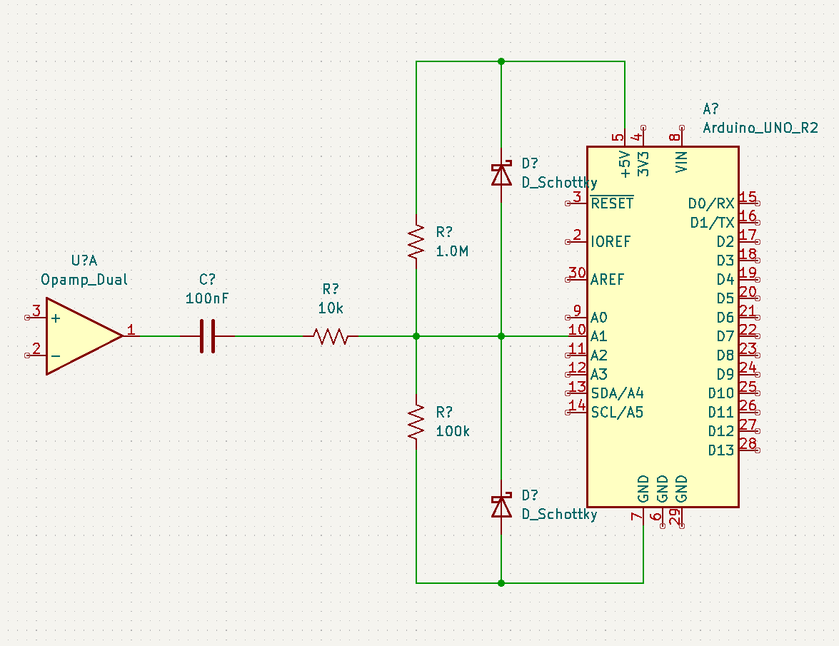
I didn't focus on optimum component values, those need some analysis, but these should at least work. The 10k resistor in combination with the Schottky diodes, protect the ADC input from voltage overload.
The increased sensitivity of the ADC input circuit means, it's possible to use a single supply 5V op amp.
Thanks for the help guys, I got the input working and have begun to work on the output.
The diagram below shows an Uno but it is actually a Zero and the DAC is a BU9480F
Your 'Rinput' is connected wrong, in series with the input. One end is supposed to go to the input, the other end to a reference voltage that should be half the supply voltage (in this case, ground). Do you really have dual supplies? It's not necessary, you can make your own virtual ground with a voltage divider.
I'm sorry, but that is plainly evident in examples in most data sheets, and in any Op amp tutorial 101. I say this because the number one design mistake beginners make, is to not do exhaustive research.
What is the purpose of the elaborate resistor network between the preamplifier and the Arduino?
A schematic with no values written on it is not particularly useful, except as an academic demonstration of something.
It's highly doubtful that the posted circuit behaves as you expect, so it's not really time to move on to the output.
The diagram is slightly wrong, this shows the actual input. I must have forgot to update the input half when I was editing it.
Im using circuit-diagram.org where I could not find a Zero or the DAC, so what is representing the DAC is just a random thing I made on MS paint lol.
Im using dual supplies because when I first started the project and ordered my components, I had pretty much no knowledge of how op amps worked other than a very small segment in a university module. I still dont really understand a lot about them and unfortunately the concept of virtual ground isnt really going into my head when Ive tried to research it.
I definitely understand that some of my questions/problems may seem stupid/self inflicted so I dont feel trodden on, not at all - I appreciate the help.
Apologies for the output section looking funky, I ran out of space. To explain, pins 1 and 4 combine through identical resistors before passing to a high-pass filter on the output, removing the DC offset.
It's looking better. You need to give unique identifiers to each component, so we can discuss them without using phrases like, "the resistor that is..".
The thing that leaps out for me, the unnecessarily complex and unexplained resistor network, "Radd1" and "RD1" and "Rfilter".
Still not knowing your exact requirements, I can guess that you only need half the number of resistors there. It would be helpful if you explained your intentions for it.
Also is there a reason you declined to include the protection diodes I suggested? A link was provided in reply #3.
Also, there are still no component values on your diagram, this is a major omission.
What is "Routguitar"? Normally there is no series resistance in an audio input. Depending on its value, it's possible you are reducing the gain and then boosting it in the op amp. It's a good idea to have an amp at least as a buffer, as the guitar should see about 1M input impedance.
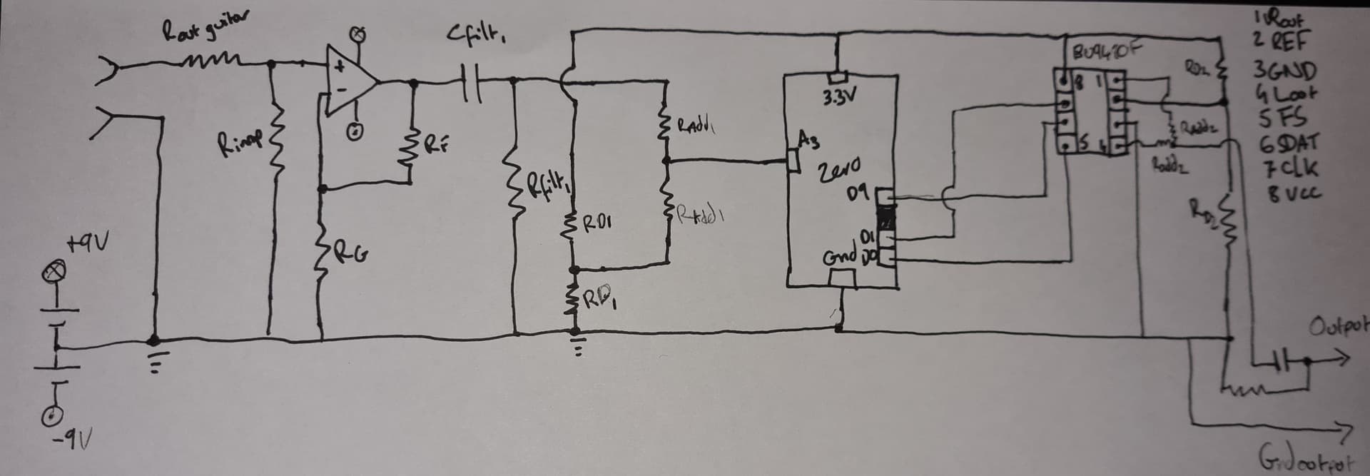
This is the diagram with values. Ive just been using the overcomplicated names just so that it is easier for me to reference them in terms of what their function is.
I currently have a limited supply of resistors otherwise I would have probably used 100k ones for the second divider too. Ive played around with the values of the adding resistors (Radd1 etc) and they dont seem to be making much of a difference, other than a very slight fluctuation in the measured signal - the 100k/1k selection is mainly based off of where I have spare resistors.
I plan to add in the protection diodes when I get more components, as I dont have any diodes currently. I also plan on perhaps getting rid of the second voltage divider.
Currently the second voltage divider is used because I had initially used only one to power both the offset and the DAC, but the guitar signal seemed to bypass through so that the reference voltage was changing. I worked this out simply by measuring the voltage that was being applied to the reference pin.
This image shows how the signal was flowing to the pin, and the circle is where I plan on adding a diode to simplify the circuit.
I believe that I could use a diode to hold the divider at Vcc/2 despite the incoming signal? Though I could be very wrong about that.
It doesn't explain why such resistor is used.. honestly would steer away from such sites when considering this design. It will only add confusion.
You may be able to use one voltage reference divider chain to bias both input and output circuits. But it must isolate the two. You have not. Because a resistor network does not present a low impedance, this is a tricky situation. I suggest just using separate references for input and output. It's not worth the risk and head scratching for a beginner.