

this is my second arduino project. another persistence of vision. i feel like it's much better than my other project, so i am quite excited.
However, it's still a work in progress and tons of little things to fix/ reprogram. i just feel like showing off a little bit first ;D
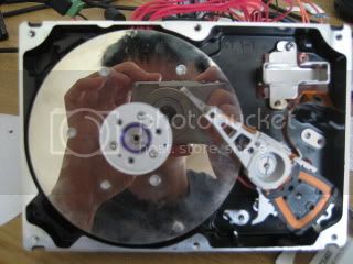
this is a hard drive clock. I've saw some cool ones out there, so i wanted to make one myself. However, the ones i saw was either numeric time display (with numbers cut out on a plate) or hand/dials (with a silt cut on the plate) Instead of choosing just one, i wanted to make one that's capable of displaying time/ message in any way i want to.
What i have done:
-- i have drilled 6 holes through the plate, each on a radius 60 degree apart. each a different distance from the center. or in other words, i have 6 points in polar coordinate [1,0o], [2,60o], [3,120o], [4,180o], [5,240o], [6,300o]
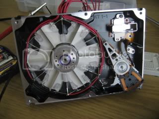
-- underneath the plate, i have divided it into 6 compartments of LEDs, each individually controlled.
-- there's a small magnet on the plate and a hallf effect sensor indexing the plate's rotation (you can even see them in the picture if you look hard enough)
-- with a little programming on our beloved arduino, we can have right compartment blinking at the right time to display 216 different "pixels"
problems i had:
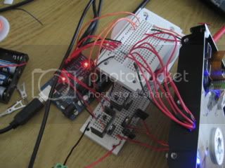
-- never worked with a stepper motor before, i had a hard time getting the hard drive spinning at first. i had stripped down hard drive to four wires in the back, so it took me a lot time to figure out which 3 to pulse (and which one was the common cathode.)
-- after much frustration and fruitless tries, i realized 5 volt with 40ma per pin was the problem. (who knew motors need so much power? :))
so i added some 2N2222 transistor to amplify the current.
-- after i FINALLY got the motor running (it was also really tricky finding the right increment to accelerate it from rest) my resistors / 2N2222 started smoking. :o i looked at the datasheets again. i guess they weren't rated for 5v & 800ma (4 watts). opps. i bought some extra high power transistors to solve the problem. so it's 4ma from arduino amplify to 50ma from 2N2222 to ~1.2A from a power transistor. appearntly the setup is called a darlington pair
-- everything is running great. then suddenly everything stops. i keep thinking things are overheated, but apparently AAs batteries run out of charge rather fast. lol i now haev it pluged into an ac adapter
here's some more pictures, i shall post up the code or more pictures after i tidy things up and fix those leaking light dots.
next step: fixes those darn leaking light, or perhaps make it RGB?
 |
 |
|---|---|
 |
 |