Hardware-based-PWM nRF52_MBED_PWM library for Nano_33_BLE

nRF52_MBED_PWM library GitHub release
How To Install Using Arduino Library Manager


Features

This library enables you to use Hardware-based PWM to create and output PWM to pins on an nRF52840-based Nano_33_BLE board.

The most important feature is they're purely hardware-based PWM channels. Therefore, the frequency can be higher than hybrid or software-based PWM, and their executions are not blocked by bad-behaving functions / tasks. This important feature is absolutely necessary for mission-critical tasks.

The PWM_Multi will demonstrate the usage of multichannel PWM using multiple Hardware-PWM channels. The 4 independent Hardware-PWMs are used to control 4 different PWM outputs, with totally independent frequencies and dutycycles. You can start, stop, change and restore the settings of any PWM channel on-the-fly


Currently supported Boards

  1. Nano_33_BLE boards, using ArduinoCore-mbed mbed_nano core


Changelog

Initial Releases v1.0.0

  1. Initial coding to support Nano_33_BLE boards, using ArduinoCore-mbed mbed_nano core

Examples:

  1. PWM_Multi
  2. PWM_Multi_Args
  3. multiFileProject

Debug Terminal Output Samples

1. PWM_Single on Nano_33_BLE

The following is the sample terminal output when running example PWM_Multi on Nano_33_BLE to demonstrate how to start multiple PWM channels, then stop, change, restore the PWM settings on-the-fly.

Starting PWM_Multi on Nano_33_BLE
nRF52_MBED_PWM v1.0.0
[PWM] Freq = 1000.00, 	DutyCycle % = 50.00, 	DutyCycle = 0.50, 	Pin = 2
[PWM] Freq = 2500.00, 	DutyCycle % = 50.00, 	DutyCycle = 0.50, 	Pin = 3
[PWM] Freq = 4000.00, 	DutyCycle % = 50.00, 	DutyCycle = 0.50, 	Pin = 4
[PWM] Freq = 5000.00, 	DutyCycle % = 50.00, 	DutyCycle = 0.50, 	Pin = 5

==========================================================================================================
PW (us) 0	PW (us) 1	PW (us) 2	PW (us) 3	
==========================================================================================================
500.00		200.00		125.00		100.00		
Stop all PWM
0.00		0.00		0.00		0.00		
0.00		0.00		0.00		0.00		
Change all PWM
125.00		50.00		31.25		25.00		
125.00		50.00		31.25		25.00		
Restore all PWM
500.00		200.00		125.00		100.00		
500.00		200.00		125.00		100.00		
Stop all PWM
0.00		0.00		0.00		0.00		
0.00		0.00		0.00		0.00		
Change all PWM
125.00		50.00		31.25		25.00		
125.00		50.00		31.25		25.00		
Restore all PWM
500.00		200.00		125.00		100.00		
500.00		200.00		125.00		100.00	

Hello @khoih-prog

Thank you for developing this. It has come with perfect timing. I really could use it for my automotive PWM fan control which runs at 10 Hz.

I am tying your PMW_Single code and not getting it to compile, see error message below. I also found that I needed to rename the include file to "nRF52_MBED_Slow_PWM" because that is the file names and directories as installed. Ultimately I need to get the attached file to work with the Nano 33 BLE. It currently works with an UNO.

I would certainly appreciate whatever you can do.

#include <PWM.h>
// Note for low frequency < 31Hz,the high resolution pwmWriteHR() must be used with 16 bit PWM Value
//For the RoboRed only pins 9 and 10 can be used with 16 bit resolution

int RadPin = A0;
int CondPin = A1;
int AuxPin = A2;

int RadVals[6] = {0, 0, 0, 0, 0, 0};
int CondVals[6] = {0, 0, 0, 0, 0, 0};
int AuxVals[6] = {0, 0, 0, 0, 0, 0};

// 10 bit temperature equivolents for radiator sensor
int Rad20 = 444;    //85C
int Rad30 = 484;    //90C
int Rad40 = 524;    //95C
int Rad50 = 562;    //100C
int Rad60 = 599;    //105C
int Rad70 = 635;    //110C
int Rad80 = 668;    //115C
int Rad90 = 699;    //120C

// 10 bit temperature equivolents for condenser sensor
int Cnd20 = 391;    //40C
int Cnd30 = 440;    //45C
int Cnd40 = 489;    //50C
int Cnd50 = 537;    //55C
int Cnd60 = 583;    //60C
int Cnd70 = 627;    //65C
int Cnd80 = 668;    //70C
int Cnd90 = 706;    //75C

int Aux20 = 0;
int Aux30 = 0;
int Aux40 = 0;
int Aux50 = 0;
int Aux60 = 0;
int Aux70 = 0;
int Aux80 = 0;
int Aux90 = 0;

int RadSpeed = 10;
int CondSpeed = 10;
int AuxSpeed = 10;

int FanSpeed = 10;    // Set fan to 10% PWM = off
int FanPin = 9;       // Set Fan pin
int16_t PWMVal;
int32_t frequency = 10;

int t1;

void setup() {
  // put your setup code here, to run once:
  pinMode(RadPin, INPUT);
  Serial.begin(9600);
  InitTimersSafe()

  //sets the frequency for the specified pin
  ;  bool success = SetPinFrequencySafe(FanPin, frequency);

  //if the pin frequency was set successfully, pin 13 turn on. Pin 13 can be used to light an LED etc.
  if (success) {
    pinMode(13, OUTPUT);
    digitalWrite(13, HIGH);
  }

}

void loop() {
  // put your main code here, to run repeatedly:
  //this code prints sensor value to the console
  Serial.print("Rad pin input = "); Serial.println(RadVals[0]);
  Serial.print("Cond pin input = "); Serial.println(CondVals[0]);
  Serial.print("Aux pin input = "); Serial.println(AuxVals[0]);
  Serial.println("Yo1");
  Serial.println();
  // delay(1000);
  // t1=millis();
  // do {
  // } while (millis()-t1 <1000);

  // initialize values
  RadVals[5] = 0;
  CondVals[5] = 0;
  AuxVals[5] = 0;

  //read sensor value and set upper limit cap
  //for (int i = 1; i <= 5; i++)  {

  int i = 0;
  do {
    // Find 5 data points
    RadVals[i] = analogRead(RadPin);
    CondVals[i] = analogRead(CondPin);
    AuxVals[i] = analogRead(AuxPin);

    Serial.print("Rad pin input stored = "); Serial.println(RadVals[i]);
    Serial.print("Cond pin input stored = "); Serial.println(CondVals[i]);
    Serial.print("Aux pin input stored = "); Serial.println(AuxVals[i]);
    Serial.println(i);
    Serial.println("Yo2");
    Serial.println();
    // delay(1000);

    //Serial.print("Rad pin input before sum = "); Serial.println(RadVals[5]);
    //Serial.println("Yo25");
    //Serial.println();

    // sum all 5 data points
    RadVals[5] = RadVals[5] + RadVals[i];
    CondVals[5] = CondVals[5] + CondVals[i];
    AuxVals[5] = AuxVals[5] + AuxVals[i];

    Serial.print("Rad pin input sum = "); Serial.println(RadVals[5]);
    Serial.print("Cond pin input sum = "); Serial.println(CondVals[5]);
    Serial.print("Aux pin input sum = "); Serial.println(AuxVals[5]);
    Serial.println(i);
    Serial.println("Yo3");
    Serial.println();
    // delay(1000);


    i = i + 1;

  } while (i < 5);

  // Find Average of 5 data points
  RadVals[5] = RadVals[5] / 5;
  CondVals[5] = CondVals[5] / 5;
  AuxVals[5] = AuxVals[5] / 5;

  Serial.print("Rad pin input Average = "); Serial.println(RadVals[5]);
  Serial.print("Cond pin input Average = "); Serial.println(CondVals[5]);
  Serial.print("Aux pin input Average = "); Serial.println(AuxVals[5]);
  Serial.println(i);
  Serial.println("Yo4");
  Serial.println();
  // delay(1000);

  if (RadVals[5] < Rad20) RadSpeed = 10;
  if (RadVals[5] < Rad30 and RadVals[5] >= Rad20) RadSpeed = 20;
  if (RadVals[5] < Rad40 and RadVals[5] >= Rad30) RadSpeed = 30;
  if (RadVals[5] < Rad50 and RadVals[5] >= Rad40) RadSpeed = 40;
  if (RadVals[5] < Rad60 and RadVals[5] >= Rad50) RadSpeed = 50;
  if (RadVals[5] < Rad70 and RadVals[5] >= Rad60) RadSpeed = 60;
  if (RadVals[5] < Rad80 and RadVals[5] >= Rad70) RadSpeed = 70;
  if (RadVals[5] < Rad90 and RadVals[5] >= Rad80) RadSpeed = 80;
  if (RadVals[5] >= Rad90) RadSpeed = 90;

  if (CondVals[5] < Cnd20) CondSpeed = 10;
  if (CondVals[5] < Cnd30 and CondVals[5] >= Cnd20) CondSpeed = 20;
  if (CondVals[5] < Cnd40 and CondVals[5] >= Cnd30) CondSpeed = 30;
  if (CondVals[5] < Cnd50 and CondVals[5] >= Cnd40) CondSpeed = 40;
  if (CondVals[5] < Cnd60 and CondVals[5] >= Cnd50) CondSpeed = 50;
  if (CondVals[5] < Cnd70 and CondVals[5] >= Cnd60) CondSpeed = 60;
  if (CondVals[5] < Cnd80 and CondVals[5] >= Cnd70) CondSpeed = 70;
  if (CondVals[5] < Cnd90 and CondVals[5] >= Cnd80) CondSpeed = 80;
  if (CondVals[5] >= Cnd90) CondSpeed = 90;

  if (AuxVals[5] < Aux20) AuxSpeed = 10;
  if (AuxVals[5] < Aux30 and AuxVals[5] >= Aux20) AuxSpeed = 20;
  if (AuxVals[5] < Aux40 and AuxVals[5] >= Aux30) AuxSpeed = 30;
  if (AuxVals[5] < Aux50 and AuxVals[5] >= Aux40) AuxSpeed = 40;
  if (AuxVals[5] < Aux60 and AuxVals[5] >= Aux50) AuxSpeed = 50;
  if (AuxVals[5] < Aux70 and AuxVals[5] >= Aux60) AuxSpeed = 60;
  if (AuxVals[5] < Aux80 and AuxVals[5] >= Aux70) AuxSpeed = 70;
  if (AuxVals[5] < Aux90 and AuxVals[5] >= Aux80) AuxSpeed = 80;
  if (AuxVals[5] >= Aux90) AuxSpeed = 90;

  FanSpeed = max(RadSpeed, CondSpeed);
  //map and assign pwm values to the fan output 0 to 65535 corresponds to 0 to 100%
  PWMVal = map(FanSpeed, 0, 100, 0, 65535);

  Serial.print("Rad pin input Average = "); Serial.println(RadVals[5]);
  Serial.print("Cond pin input Average = "); Serial.println(CondVals[5]);
  Serial.print("Aux pin input Average = "); Serial.println(AuxVals[5]);
  Serial.print("Fan Speed = "); Serial.println(FanSpeed);
  Serial.print("PMWval = "); Serial.println(PWMVal);
  Serial.println("Yo4");
  Serial.println();
  // delay(1000);


  //write the PWM value to the pwm output pin
  pwmWriteHR(FanPin, PWMVal);


}

First, you have to select Tools->Arduino Mbed OS Nano Boards->Board: "Arduino Nano 33 BLE" to compile, using the ArduinoCore-mbed core v2.8.0+

Then you have to convert your program, written for AVR boards (UNO/Nano/Mega, etc.) by yourself or ask for help in separate thread.

Anyway, this the the revised code, written for Nano_33_BLE board. Please modify as necessary, test and report the results here as I don't have the same board or settings to test.

Still messy, just little bit better

#define _PWM_LOGLEVEL_       2

// To be included only in main(), .ino with setup() to avoid `Multiple Definitions` Linker Error
#include "nRF52_MBED_PWM.h"     // https://github.com/khoih-prog/nRF52_MBED_PWM

// Note for low frequency < 31Hz,the high resolution pwmWriteHR() must be used with 16 bit PWM Value
//For the RoboRed only pins 9 and 10 can be used with 16 bit resolution

int RadPin  = A0;
int CondPin = A1;
int AuxPin  = A2;

#define NUMBER_OF_SENSORS      5

int RadVals [NUMBER_OF_SENSORS] = {0, 0, 0, 0, 0};
int CondVals[NUMBER_OF_SENSORS] = {0, 0, 0, 0, 0};
int AuxVals [NUMBER_OF_SENSORS] = {0, 0, 0, 0, 0};

int RadValAvg  = 0;
int CondValAvg = 0;
int AuxValAvg  = 0;

#define FAKE_TESTING     false

#if FAKE_TESTING
  // Make fake temp higher to speed-up the fan in lab test
  // 10 bit temperature equivalents for radiator sensor
  int Rad20 = 444/2;    //85C
  int Rad30 = 484/2;    //90C
  int Rad40 = 524/2;    //95C
  int Rad50 = 562/2;    //100C
  int Rad60 = 599/2;    //105C
  int Rad70 = 635/2;    //110C
  int Rad80 = 668/2;    //115C
  int Rad90 = 699/2;    //120C
#else
  int Rad20 = 444;    //85C
  int Rad30 = 484;    //90C
  int Rad40 = 524;    //95C
  int Rad50 = 562;    //100C
  int Rad60 = 599;    //105C
  int Rad70 = 635;    //110C
  int Rad80 = 668;    //115C
  int Rad90 = 699;    //120C
#endif

// 10 bit temperature equivolents for condenser sensor
int Cnd20 = 391;    //40C
int Cnd30 = 440;    //45C
int Cnd40 = 489;    //50C
int Cnd50 = 537;    //55C
int Cnd60 = 583;    //60C
int Cnd70 = 627;    //65C
int Cnd80 = 668;    //70C
int Cnd90 = 706;    //75C

int Aux20 = 0;
int Aux30 = 0;
int Aux40 = 0;
int Aux50 = 0;
int Aux60 = 0;
int Aux70 = 0;
int Aux80 = 0;
int Aux90 = 0;

int RadSpeed  = 10;
int CondSpeed = 10;
int AuxSpeed  = 10;

float FanSpeed = 10;       // Set fan to 10% PWM = off
int   FanPin   = 9;        // Set Fan pin

mbed::PwmOut* pwm   = NULL;

int32_t frequency = 10;void printData(const int& index = 0)
{
  PWM_LOGINFO3("Rad(", index, ") input = ", RadVals[index]);
  PWM_LOGINFO3("Cond(", index, ") input = ", RadVals[index]);
  PWM_LOGINFO3("Aux(", index, ") input = ", RadVals[index]);
}

void printAvg()
{
  PWM_LOGWARN1("RadAvg  = ", RadValAvg);
  PWM_LOGWARN1("CondAvg = ", CondValAvg);
  PWM_LOGWARN1("AuxAvg  = ", AuxValAvg);
}

void readAnalogData(const int& index)
{
  RadVals[index]  = analogRead(RadPin);
  CondVals[index] = analogRead(CondPin);
  AuxVals[index]  = analogRead(AuxPin);

  // sum all 5 data points
  RadValAvg += RadVals [index];
  CondValAvg+= CondVals[index];
  AuxValAvg += AuxVals [index];
}

void updateCheck()
{
  int index = 0;

  RadValAvg  = 0;
  CondValAvg = 0;
  AuxValAvg  = 0;
  
  do 
  {
    // Read 5 data points
    readAnalogData(index);

    printData(index);

    index = index + 1;

  } while (index < NUMBER_OF_SENSORS);

  // Find Average of 5 data points
  RadValAvg  = RadValAvg  / NUMBER_OF_SENSORS;
  CondValAvg = CondValAvg / NUMBER_OF_SENSORS;
  AuxValAvg  = AuxValAvg  / NUMBER_OF_SENSORS;

  printAvg();

  if (RadValAvg < Rad20) RadSpeed = 10;
  if (RadValAvg < Rad30 and RadValAvg >= Rad20) RadSpeed = 20;
  if (RadValAvg < Rad40 and RadValAvg >= Rad30) RadSpeed = 30;
  if (RadValAvg < Rad50 and RadValAvg >= Rad40) RadSpeed = 40;
  if (RadValAvg < Rad60 and RadValAvg >= Rad50) RadSpeed = 50;
  if (RadValAvg < Rad70 and RadValAvg >= Rad60) RadSpeed = 60;
  if (RadValAvg < Rad80 and RadValAvg >= Rad70) RadSpeed = 70;
  if (RadValAvg < Rad90 and RadValAvg >= Rad80) RadSpeed = 80;
  if (RadValAvg >= Rad90) RadSpeed = 90;

  if (CondValAvg < Cnd20) CondSpeed = 10;
  if (CondValAvg < Cnd30 and CondValAvg >= Cnd20) CondSpeed = 20;
  if (CondValAvg < Cnd40 and CondValAvg >= Cnd30) CondSpeed = 30;
  if (CondValAvg < Cnd50 and CondValAvg >= Cnd40) CondSpeed = 40;
  if (CondValAvg < Cnd60 and CondValAvg >= Cnd50) CondSpeed = 50;
  if (CondValAvg < Cnd70 and CondValAvg >= Cnd60) CondSpeed = 60;
  if (CondValAvg < Cnd80 and CondValAvg >= Cnd70) CondSpeed = 70;
  if (CondValAvg < Cnd90 and CondValAvg >= Cnd80) CondSpeed = 80;
  if (CondValAvg >= Cnd90) CondSpeed = 90;

  if (AuxValAvg < Aux20) AuxSpeed = 10;
  if (AuxValAvg < Aux30 and AuxValAvg >= Aux20) AuxSpeed = 20;
  if (AuxValAvg < Aux40 and AuxValAvg >= Aux30) AuxSpeed = 30;
  if (AuxValAvg < Aux50 and AuxValAvg >= Aux40) AuxSpeed = 40;
  if (AuxValAvg < Aux60 and AuxValAvg >= Aux50) AuxSpeed = 50;
  if (AuxValAvg < Aux70 and AuxValAvg >= Aux60) AuxSpeed = 60;
  if (AuxValAvg < Aux80 and AuxValAvg >= Aux70) AuxSpeed = 70;
  if (AuxValAvg < Aux90 and AuxValAvg >= Aux80) AuxSpeed = 80;
  if (AuxValAvg >= Aux90) AuxSpeed = 90;

  FanSpeed = max(RadSpeed, CondSpeed);

  PWM_LOGWARN1("Fan Speed  = ", FanSpeed);

  //write the PWM value to the pwm output pin
  PWM_LOGWARN7("Freq = ", frequency, ", FanSpeed % = ", FanSpeed, ", FanSpeed = ", FanSpeed / 100, ", Pin = ", FanPin);
  setPWM(pwm, FanPin, frequency, FanSpeed);
}

#define PRINT_INTERVAL                10000L
#define UPDATE_CHECK_INTERVAL_MS      1000L

void check_status()
{
  static unsigned long print_timeout  = 0;
  static unsigned long update_timeout = 0;

  static bool LED_status = HIGH;

  // Print every PRINT_INTERVAL (10) seconds.
  if ((millis() > print_timeout) || (print_timeout == 0))
  {
    // Blink LED
    LED_status = !LED_status;
    digitalWrite(LED_BUILTIN, LED_status);
    
    printData();
    print_timeout = millis() + PRINT_INTERVAL;
  }

  if ( (millis() > update_timeout) && (millis() > UPDATE_CHECK_INTERVAL_MS) )
  {   
    updateCheck();
      
    update_timeout = millis() + UPDATE_CHECK_INTERVAL_MS;
  }
}

void setup() 
{
  // put your setup code here, to run once:
  pinMode(RadPin, INPUT);
  pinMode(FanPin, OUTPUT);
  pinMode(LED_BUILTIN, OUTPUT);
  
  Serial.begin(115200);
  while (!Serial);

  delay(200);

  Serial.print(F("\nStarting Car_Fan_Control using ")); Serial.println(BOARD_NAME);
  Serial.println(nRF52_MBED_PWM_VERSION);
  
  digitalWrite(LED_BUILTIN, HIGH);
}

void loop() 
{
  check_status();
}

Good Luck,

Hello-khoih

Thank you very much for your time. Did did not expect you to go and rewrite the code yourself. What I found is that when I installed the library, I had inadvertently selected the wrong library. I had installed:

nRF52_MBED_Slow_PWM.h

instead of

nRF52_MBED_PWM.h

So once I got the correct library installed the PWM_Single program worked. However changing the frequency to 10Hz did not work. The serial monitor reported 10Hz but the light was blinking at ~ 30Hz. I even tried setting it to 1Hz and it still blinked at about 30Hz. I do know that 31Hz is the lower limit for PWM without hardware libraries and it appears that the output is defaulting to that minimum.

As far as the updated code you sent me, I am not getting any PWM signal out of it at all. Please understand I am an old Fortran programmer so that code is very difficult for me to understand. If I can get the PWM_Single program to work at 10Hz I believe I can modify my program to get it to run. Attached is the serial output from PWM_Single reporting a frequency of 1Hz but the light was still blinking at about 30Hz.

23:14:07.557 ->
23:14:07.557 -> Starting PWM_Single on Nano 33 BLE
23:14:07.557 -> nRF52_MBED_PWM v1.0.1
23:14:07.557 -> [PWM] Freq = 1.00, DutyCycle % = 50.00, DutyCycle = 0.50, Pin = 7
23:14:07.604 ->
23:14:07.604 -> ============================================
23:14:07.604 -> PW (us) DutyCycle Period (uS)
23:14:07.604 -> ============================================
23:14:08.718 -> Stop PWM
23:14:17.596 -> 0.00 0.00 1000.00
23:14:27.624 -> 0.00 0.00 1000.00
23:14:28.726 -> Change PWM
23:14:37.621 -> 8191.75 25.00 32767.00
23:14:47.648 -> 8191.75 25.00 32767.00
23:14:48.698 -> Restore PWM

Buy the way what is the ```
nRF52_MBED_Slow_PWM.h

library used for?

I currently don't have Nano_33_BLE now to test and know where/what is wrong. But I port the code to much cheaper RP2040 ($4), and is working OK at 10Hz, using my RP2040_PWM library.

I don't know when I can buy / have the new Nano_33_BLE to test and be sure. So it's better to move to RP2040 now.

Hereafter are the code and the oscilloscope pictures to show that the code is working with 10Hz PWM (100ms period)

My nRF52_MBED_Slow_PWM was designed for very slow PWM-frequency applications, such as yours, with frequency from much smaller than 1Hz to 500-1000Hz.

Code

#define _PWM_LOGLEVEL_       2

// To be included only in main(), .ino with setup() to avoid `Multiple Definitions` Linker Error
#include "RP2040_PWM.h"    // https://github.com/khoih-prog/RP2040_PWM

// Note for low frequency < 31Hz,the high resolution pwmWriteHR() must be used with 16 bit PWM Value
//For the RoboRed only pins 9 and 10 can be used with 16 bit resolution

int RadPin  = A0;
int CondPin = A1;
int AuxPin  = A2;

#define NUMBER_OF_SENSORS      5

int RadVals [NUMBER_OF_SENSORS] = {0, 0, 0, 0, 0};
int CondVals[NUMBER_OF_SENSORS] = {0, 0, 0, 0, 0};
int AuxVals [NUMBER_OF_SENSORS] = {0, 0, 0, 0, 0};

int RadValAvg  = 0;
int CondValAvg = 0;
int AuxValAvg  = 0;

#define FAKE_TESTING     false  //true

#if FAKE_TESTING
  // Make fake temp higher to speed-up the fan in lab test
  // 10 bit temperature equivalents for radiator sensor
  int Rad20 = 444/2;    //85C
  int Rad30 = 484/2;    //90C
  int Rad40 = 524/2;    //95C
  int Rad50 = 562/2;    //100C
  int Rad60 = 599/2;    //105C
  int Rad70 = 635/2;    //110C
  int Rad80 = 668/2;    //115C
  int Rad90 = 699/2;    //120C
#else
  int Rad20 = 444;    //85C
  int Rad30 = 484;    //90C
  int Rad40 = 524;    //95C
  int Rad50 = 562;    //100C
  int Rad60 = 599;    //105C
  int Rad70 = 635;    //110C
  int Rad80 = 668;    //115C
  int Rad90 = 699;    //120C
#endif

// 10 bit temperature equivalents for condenser sensor
int Cnd20 = 391;    //40C
int Cnd30 = 440;    //45C
int Cnd40 = 489;    //50C
int Cnd50 = 537;    //55C
int Cnd60 = 583;    //60C
int Cnd70 = 627;    //65C
int Cnd80 = 668;    //70C
int Cnd90 = 706;    //75C

int Aux20 = 0;
int Aux30 = 0;
int Aux40 = 0;
int Aux50 = 0;
int Aux60 = 0;
int Aux70 = 0;
int Aux80 = 0;
int Aux90 = 0;

int RadSpeed  = 10;
int CondSpeed = 10;
int AuxSpeed  = 10;

float FanSpeed = 10;       // Set fan to 10% PWM = off
int   FanPin   = 15;       // Set Fan pin

int32_t frequency = 10;

//mbed::PwmOut* pwm   = NULL;
RP2040_PWM* PWM_Instance;

void printData(const int& index = 0)
{
  PWM_LOGINFO3("Rad(", index, ") input = ", RadVals[index]);
  PWM_LOGINFO3("Cond(", index, ") input = ", RadVals[index]);
  PWM_LOGINFO3("Aux(", index, ") input = ", RadVals[index]);
}

void printAvg()
{
  PWM_LOGWARN1("RadAvg  = ", RadValAvg);
  PWM_LOGWARN1("CondAvg = ", CondValAvg);
  PWM_LOGWARN1("AuxAvg  = ", AuxValAvg);
}

void readAnalogData(const int& index)
{
  RadVals[index]  = analogRead(RadPin);
  CondVals[index] = analogRead(CondPin);
  AuxVals[index]  = analogRead(AuxPin);

  // sum all 5 data points
  RadValAvg += RadVals [index];
  CondValAvg+= CondVals[index];
  AuxValAvg += AuxVals [index];
}

void updateCheck()
{
  int index = 0;

  RadValAvg  = 0;
  CondValAvg = 0;
  AuxValAvg  = 0;
  
  do 
  {
    // Read 5 data points
    readAnalogData(index);

    printData(index);

    index = index + 1;

  } while (index < NUMBER_OF_SENSORS);

  // Find Average of 5 data points
  RadValAvg  = RadValAvg  / NUMBER_OF_SENSORS;
  CondValAvg = CondValAvg / NUMBER_OF_SENSORS;
  AuxValAvg  = AuxValAvg  / NUMBER_OF_SENSORS;

  printAvg();

  if (RadValAvg < Rad20) RadSpeed = 10;
  if (RadValAvg < Rad30 and RadValAvg >= Rad20) RadSpeed = 20;
  if (RadValAvg < Rad40 and RadValAvg >= Rad30) RadSpeed = 30;
  if (RadValAvg < Rad50 and RadValAvg >= Rad40) RadSpeed = 40;
  if (RadValAvg < Rad60 and RadValAvg >= Rad50) RadSpeed = 50;
  if (RadValAvg < Rad70 and RadValAvg >= Rad60) RadSpeed = 60;
  if (RadValAvg < Rad80 and RadValAvg >= Rad70) RadSpeed = 70;
  if (RadValAvg < Rad90 and RadValAvg >= Rad80) RadSpeed = 80;
  if (RadValAvg >= Rad90) RadSpeed = 90;

  if (CondValAvg < Cnd20) CondSpeed = 10;
  if (CondValAvg < Cnd30 and CondValAvg >= Cnd20) CondSpeed = 20;
  if (CondValAvg < Cnd40 and CondValAvg >= Cnd30) CondSpeed = 30;
  if (CondValAvg < Cnd50 and CondValAvg >= Cnd40) CondSpeed = 40;
  if (CondValAvg < Cnd60 and CondValAvg >= Cnd50) CondSpeed = 50;
  if (CondValAvg < Cnd70 and CondValAvg >= Cnd60) CondSpeed = 60;
  if (CondValAvg < Cnd80 and CondValAvg >= Cnd70) CondSpeed = 70;
  if (CondValAvg < Cnd90 and CondValAvg >= Cnd80) CondSpeed = 80;
  if (CondValAvg >= Cnd90) CondSpeed = 90;

  if (AuxValAvg < Aux20) AuxSpeed = 10;
  if (AuxValAvg < Aux30 and AuxValAvg >= Aux20) AuxSpeed = 20;
  if (AuxValAvg < Aux40 and AuxValAvg >= Aux30) AuxSpeed = 30;
  if (AuxValAvg < Aux50 and AuxValAvg >= Aux40) AuxSpeed = 40;
  if (AuxValAvg < Aux60 and AuxValAvg >= Aux50) AuxSpeed = 50;
  if (AuxValAvg < Aux70 and AuxValAvg >= Aux60) AuxSpeed = 60;
  if (AuxValAvg < Aux80 and AuxValAvg >= Aux70) AuxSpeed = 70;
  if (AuxValAvg < Aux90 and AuxValAvg >= Aux80) AuxSpeed = 80;
  if (AuxValAvg >= Aux90) AuxSpeed = 90;

  FanSpeed = max(RadSpeed, CondSpeed);

  PWM_LOGWARN1("Fan Speed  = ", FanSpeed);

  //write the PWM value to the pwm output pin
  PWM_LOGWARN7("Freq = ", frequency, ", FanSpeed % = ", FanSpeed, ", FanSpeed = ", FanSpeed / 100, ", Pin = ", FanPin);
  //setPWM(pwm, FanPin, frequency, FanSpeed);
  PWM_Instance->setPWM(FanPin, frequency, FanSpeed, true);
}

#define PRINT_INTERVAL                10000L
#define UPDATE_CHECK_INTERVAL_MS      1000L

void check_status()
{
  static unsigned long print_timeout  = 0;
  static unsigned long update_timeout = 0;

  static bool LED_status = HIGH;

  // Print every PRINT_INTERVAL (10) seconds.
  if ((millis() > print_timeout) || (print_timeout == 0))
  {   
    printData();
    print_timeout = millis() + PRINT_INTERVAL;
  }

  if ( (millis() > update_timeout) && (millis() > UPDATE_CHECK_INTERVAL_MS) )
  {   
    // Blink LED
    LED_status = !LED_status;
    digitalWrite(LED_BUILTIN, LED_status);
    
    updateCheck();
      
    update_timeout = millis() + UPDATE_CHECK_INTERVAL_MS;
  }
}

void setup() 
{
  // put your setup code here, to run once:
  pinMode(RadPin, INPUT);
  pinMode(FanPin, OUTPUT);
  pinMode(LED_BUILTIN, OUTPUT);
  
  Serial.begin(115200);
  while (!Serial);

  delay(200);

  Serial.print(F("\nStarting Car_Fan_Control using ")); Serial.println(BOARD_NAME);
  Serial.println(RP2040_PWM_VERSION);

  PWM_Instance = new RP2040_PWM(FanPin, frequency, FanSpeed);
  
  digitalWrite(LED_BUILTIN, HIGH);
}

void loop() 
{
  check_status();
}

Oscilloscope pictures

10% duty-cycle / speed

80% duty-cycle / speed

Try this un-tested code using nRF52_MBED_Slow_PWM Library

#if !( ARDUINO_ARCH_NRF52840 && TARGET_NAME == ARDUINO_NANO33BLE )
  #error This code is designed to run on nRF52-based Nano-33-BLE boards using mbed-RTOS platform! Please check your Tools->Board setting.
#endif

#define _PWM_LOGLEVEL_       2

#define USING_MICROS_RESOLUTION       true    //false 

// To be included only in main(), .ino with setup() to avoid `Multiple Definitions` Linker Error
#include "nRF52_MBED_Slow_PWM.h"     // https://github.com/khoih-prog/nRF52_MBED_Slow_PWM

#define HW_TIMER_INTERVAL_US      20L

uint32_t startMicros = 0;

// For mbed nRF52, you can only select NRF52 Hardware Timer NRF_TIMER_3-NRF_TIMER_4 (3 to 4)
// If you select the already-used NRF_TIMER_0-2, it'll be auto modified to use NRF_TIMER_3

// Init NRF52 timer NRF_TIMER3
NRF52_MBED_Timer ITimer(NRF_TIMER_3);

// Init nRF52_Slow_PWM, each can service 16 different ISR-based PWM channels
NRF52_MBED_Slow_PWM ISR_PWM;

///////////////////////////////////////////////////////////////////

int RadPin  = A0;
int CondPin = A1;
int AuxPin  = A2;

#define NUMBER_OF_SENSORS      5

int RadVals [NUMBER_OF_SENSORS] = {0, 0, 0, 0, 0};
int CondVals[NUMBER_OF_SENSORS] = {0, 0, 0, 0, 0};
int AuxVals [NUMBER_OF_SENSORS] = {0, 0, 0, 0, 0};

int RadValAvg  = 0;
int CondValAvg = 0;
int AuxValAvg  = 0;

#define FAKE_TESTING     false

#if FAKE_TESTING
  // Make fake temp higher to speed-up the fan in lab test
  // 10 bit temperature equivalents for radiator sensor
  int Rad20 = 444/2;    //85C
  int Rad30 = 484/2;    //90C
  int Rad40 = 524/2;    //95C
  int Rad50 = 562/2;    //100C
  int Rad60 = 599/2;    //105C
  int Rad70 = 635/2;    //110C
  int Rad80 = 668/2;    //115C
  int Rad90 = 699/2;    //120C
#else
  int Rad20 = 444;    //85C
  int Rad30 = 484;    //90C
  int Rad40 = 524;    //95C
  int Rad50 = 562;    //100C
  int Rad60 = 599;    //105C
  int Rad70 = 635;    //110C
  int Rad80 = 668;    //115C
  int Rad90 = 699;    //120C
#endif

// 10 bit temperature equivolents for condenser sensor
int Cnd20 = 391;    //40C
int Cnd30 = 440;    //45C
int Cnd40 = 489;    //50C
int Cnd50 = 537;    //55C
int Cnd60 = 583;    //60C
int Cnd70 = 627;    //65C
int Cnd80 = 668;    //70C
int Cnd90 = 706;    //75C

int Aux20 = 0;
int Aux30 = 0;
int Aux40 = 0;
int Aux50 = 0;
int Aux60 = 0;
int Aux70 = 0;
int Aux80 = 0;
int Aux90 = 0;

int RadSpeed  = 10;
int CondSpeed = 10;
int AuxSpeed  = 10;

float FanSpeed = 10;       // Set fan to 10% PWM = off
int   FanPin   = 9;        // Set Fan pin

//////////////////////////////////////////////////////

void TimerHandler()
{ 
  ISR_PWM.run();
}

//////////////////////////////////////////////////////

// You can assign pins here. Be careful to select good pin to use or crash
// Use LED_BUILTIN to test LED blinking
//uint32_t PWM_Pin    = LED_BUILTIN;
uint32_t PWM_Pin    = FanPin;

// Channel number used to identify associated channel
int channelNum;

////////////////////////////////////////////////

//////////////////////////////////////////////////////

float frequency = 10.0f;

void printData(const int& index = 0)
{
  PWM_LOGINFO3("Rad(", index, ") input = ", RadVals[index]);
  PWM_LOGINFO3("Cond(", index, ") input = ", RadVals[index]);
  PWM_LOGINFO3("Aux(", index, ") input = ", RadVals[index]);
}

void printAvg()
{
  PWM_LOGWARN1("RadAvg  = ", RadValAvg);
  PWM_LOGWARN1("CondAvg = ", CondValAvg);
  PWM_LOGWARN1("AuxAvg  = ", AuxValAvg);
}

void readAnalogData(const int& index)
{
  RadVals[index]  = analogRead(RadPin);
  CondVals[index] = analogRead(CondPin);
  AuxVals[index]  = analogRead(AuxPin);

  // sum all 5 data points
  RadValAvg += RadVals [index];
  CondValAvg+= CondVals[index];
  AuxValAvg += AuxVals [index];
}

void updateCheck()
{
  int index = 0;

  RadValAvg  = 0;
  CondValAvg = 0;
  AuxValAvg  = 0;
  
  do 
  {
    // Read 5 data points
    readAnalogData(index);

    printData(index);

    index = index + 1;

  } while (index < NUMBER_OF_SENSORS);

  // Find Average of 5 data points
  RadValAvg  = RadValAvg  / NUMBER_OF_SENSORS;
  CondValAvg = CondValAvg / NUMBER_OF_SENSORS;
  AuxValAvg  = AuxValAvg  / NUMBER_OF_SENSORS;

  printAvg();

  if (RadValAvg < Rad20) RadSpeed = 10;
  if (RadValAvg < Rad30 and RadValAvg >= Rad20) RadSpeed = 20;
  if (RadValAvg < Rad40 and RadValAvg >= Rad30) RadSpeed = 30;
  if (RadValAvg < Rad50 and RadValAvg >= Rad40) RadSpeed = 40;
  if (RadValAvg < Rad60 and RadValAvg >= Rad50) RadSpeed = 50;
  if (RadValAvg < Rad70 and RadValAvg >= Rad60) RadSpeed = 60;
  if (RadValAvg < Rad80 and RadValAvg >= Rad70) RadSpeed = 70;
  if (RadValAvg < Rad90 and RadValAvg >= Rad80) RadSpeed = 80;
  if (RadValAvg >= Rad90) RadSpeed = 90;

  if (CondValAvg < Cnd20) CondSpeed = 10;
  if (CondValAvg < Cnd30 and CondValAvg >= Cnd20) CondSpeed = 20;
  if (CondValAvg < Cnd40 and CondValAvg >= Cnd30) CondSpeed = 30;
  if (CondValAvg < Cnd50 and CondValAvg >= Cnd40) CondSpeed = 40;
  if (CondValAvg < Cnd60 and CondValAvg >= Cnd50) CondSpeed = 50;
  if (CondValAvg < Cnd70 and CondValAvg >= Cnd60) CondSpeed = 60;
  if (CondValAvg < Cnd80 and CondValAvg >= Cnd70) CondSpeed = 70;
  if (CondValAvg < Cnd90 and CondValAvg >= Cnd80) CondSpeed = 80;
  if (CondValAvg >= Cnd90) CondSpeed = 90;

  if (AuxValAvg < Aux20) AuxSpeed = 10;
  if (AuxValAvg < Aux30 and AuxValAvg >= Aux20) AuxSpeed = 20;
  if (AuxValAvg < Aux40 and AuxValAvg >= Aux30) AuxSpeed = 30;
  if (AuxValAvg < Aux50 and AuxValAvg >= Aux40) AuxSpeed = 40;
  if (AuxValAvg < Aux60 and AuxValAvg >= Aux50) AuxSpeed = 50;
  if (AuxValAvg < Aux70 and AuxValAvg >= Aux60) AuxSpeed = 60;
  if (AuxValAvg < Aux80 and AuxValAvg >= Aux70) AuxSpeed = 70;
  if (AuxValAvg < Aux90 and AuxValAvg >= Aux80) AuxSpeed = 80;
  if (AuxValAvg >= Aux90) AuxSpeed = 90;

  FanSpeed = max(RadSpeed, CondSpeed);

  PWM_LOGWARN1("Fan Speed  = ", FanSpeed);

  //write the PWM value to the pwm output pin
  PWM_LOGWARN5("Freq = ", frequency, ", FanSpeed % = ", FanSpeed, ", Pin = ", FanPin);

  if (!ISR_PWM.modifyPWMChannel(channelNum, PWM_Pin, frequency, FanSpeed))
  {
    Serial.print(F("modifyPWMChannel error"));
  }
}

#define PRINT_INTERVAL                10000L
#define UPDATE_CHECK_INTERVAL_MS      1000L

void check_status()
{
  static unsigned long print_timeout  = 0;
  static unsigned long update_timeout = 0;

  static bool LED_status = HIGH;

  // Print every PRINT_INTERVAL (10) seconds.
  if ((millis() > print_timeout) || (print_timeout == 0))
  {   
    printData();
    print_timeout = millis() + PRINT_INTERVAL;
  }

  if ( (millis() > update_timeout) && (millis() > UPDATE_CHECK_INTERVAL_MS) )
  {   
    // Blink LED
    LED_status = !LED_status;
    digitalWrite(LED_BUILTIN, LED_status);
     
    updateCheck();
      
    update_timeout = millis() + UPDATE_CHECK_INTERVAL_MS;
  }
}

void setup() 
{
  // put your setup code here, to run once:
  pinMode(RadPin, INPUT);
  pinMode(FanPin, OUTPUT);
  pinMode(LED_BUILTIN, OUTPUT);
  
  Serial.begin(115200);
  while (!Serial);

  delay(200);

  Serial.print(F("\nStarting Car_Fan_Control using ")); Serial.println(BOARD_NAME);
  Serial.println(NRF52_MBED_SLOW_PWM_VERSION);
  
  digitalWrite(LED_BUILTIN, HIGH);

  // Interval in microsecs
  if (ITimer.attachInterruptInterval(HW_TIMER_INTERVAL_US, TimerHandler))
  {
    startMicros = micros();
    Serial.print(F("Starting ITimer OK, micros() = ")); Serial.println(startMicros);
  }
  else
    Serial.println(F("Can't set ITimer. Select another freq. or timer"));

  channelNum = ISR_PWM.setPWM(PWM_Pin, frequency, FanSpeed);  
}

void loop() 
{
  check_status();
}

Thank you khoig.

That was very successful. I had to make a few changes to get it to run my fan but very minimal.

I changed

 PWM_LOGINFO3("Rad(", index, ") input = ", RadVals[index]);
 PWM_LOGINFO3("Cond(", index, ") input = ", RadVals[index]);
 PWM_LOGINFO3("Aux(", index, ") input = ", RadVals[index]);

to:

  PWM_LOGINFO3("Rad(", index, ") input = ", RadVals[index]);
  PWM_LOGINFO3("Cond(", index, ") input = ", CondVals[index]);
  PWM_LOGINFO3("Aux(", index, ") input = ", AuxVals[index]);

I also had to comment out the

while (!Serial);

Otherwise it would not run my fan unless connected to a USB cable.

[code]
#if !( ARDUINO_ARCH_NRF52840 && TARGET_NAME == ARDUINO_NANO33BLE )
  #error This code is designed to run on nRF52-based Nano-33-BLE boards using mbed-RTOS platform! Please check your Tools->Board setting.
#endif

#define _PWM_LOGLEVEL_       2

#define USING_MICROS_RESOLUTION       true    //false 

// To be included only in main(), .ino with setup() to avoid `Multiple Definitions` Linker Error
#include "nRF52_MBED_Slow_PWM.h"     // https://github.com/khoih-prog/nRF52_MBED_Slow_PWM

#define HW_TIMER_INTERVAL_US      20L

uint32_t startMicros = 0;

// For mbed nRF52, you can only select NRF52 Hardware Timer NRF_TIMER_3-NRF_TIMER_4 (3 to 4)
// If you select the already-used NRF_TIMER_0-2, it'll be auto modified to use NRF_TIMER_3

// Init NRF52 timer NRF_TIMER3
NRF52_MBED_Timer ITimer(NRF_TIMER_3);

// Init nRF52_Slow_PWM, each can service 16 different ISR-based PWM channels
NRF52_MBED_Slow_PWM ISR_PWM;

///////////////////////////////////////////////////////////////////

int RadPin  = A0;
int CondPin = A1;
int AuxPin  = A2;

#define NUMBER_OF_SAMPLES      5

int RadVals [NUMBER_OF_SAMPLES] = {0, 0, 0, 0, 0};
int CondVals[NUMBER_OF_SAMPLES] = {0, 0, 0, 0, 0};
int AuxVals [NUMBER_OF_SAMPLES] = {0, 0, 0, 0, 0};

int RadValAvg  = 0;
int CondValAvg = 0;
int AuxValAvg  = 0;

#define FAKE_TESTING     false

#if FAKE_TESTING
  // Make fake temp higher to speed-up the fan in lab test
  // 10 bit temperature equivalents for radiator sensor
  int Rad20 = 444;    //85C
  int Rad30 = 484;    //90C
  int Rad40 = 524;    //95C
  int Rad50 = 562;    //100C
  int Rad60 = 599;    //105C
  int Rad70 = 635;    //110C
  int Rad80 = 668;    //115C
  int Rad90 = 699;    //120C
#else
  int Rad20 = 444;    //85C
  int Rad30 = 484;    //90C
  int Rad40 = 524;    //95C
  int Rad50 = 562;    //100C
  int Rad60 = 599;    //105C
  int Rad70 = 635;    //110C
  int Rad80 = 668;    //115C
  int Rad90 = 699;    //120C
#endif

// 10 bit temperature equivolents for condenser sensor
int Cnd20 = 391;    //40C
int Cnd30 = 440;    //45C
int Cnd40 = 489;    //50C
int Cnd50 = 537;    //55C
int Cnd60 = 583;    //60C
int Cnd70 = 627;    //65C
int Cnd80 = 668;    //70C
int Cnd90 = 706;    //75C

int Aux20 = 0;
int Aux30 = 0;
int Aux40 = 0;
int Aux50 = 0;
int Aux60 = 0;
int Aux70 = 0;
int Aux80 = 0;
int Aux90 = 0;

int RadSpeed  = 10;
int CondSpeed = 10;
int AuxSpeed  = 10;

float FanSpeed = 10;       // Set fan to 10% PWM = off
int   FanPin   = 9;        // Set Fan pin

//////////////////////////////////////////////////////

void TimerHandler()
{ 
  ISR_PWM.run();
}

//////////////////////////////////////////////////////

// You can assign pins here. Be careful to select good pin to use or crash
// Use LED_BUILTIN to test LED blinking
//uint32_t PWM_Pin    = LED_BUILTIN;
uint32_t PWM_Pin    = FanPin;

// Channel number used to identify associated channel
int channelNum;

////////////////////////////////////////////////

//////////////////////////////////////////////////////

float frequency = 10.0f;

void printData(const int& index = 0)
{
  PWM_LOGINFO3("Rad(", index, ") input = ", RadVals[index]);
  PWM_LOGINFO3("Cond(", index, ") input = ", CondVals[index]);
  PWM_LOGINFO3("Aux(", index, ") input = ", AuxVals[index]);
}

void printAvg()
{
  PWM_LOGWARN1("RadAvg  = ", RadValAvg);
  PWM_LOGWARN1("CondAvg = ", CondValAvg);
  PWM_LOGWARN1("AuxAvg  = ", AuxValAvg);
}

void readAnalogData(const int& index)
{
  RadVals[index]  = analogRead(RadPin);
  CondVals[index] = analogRead(CondPin);
  AuxVals[index]  = analogRead(AuxPin);

  // sum all 5 data points
  RadValAvg += RadVals [index];
  CondValAvg+= CondVals[index];
  AuxValAvg += AuxVals [index];
}

void updateCheck()
{
  int index = 0;

  RadValAvg  = 0;
  CondValAvg = 0;
  AuxValAvg  = 0;
  
  do 
  {
    // Read 5 data points
    readAnalogData(index);

    printData(index);

    index = index + 1;

  } while (index < NUMBER_OF_SAMPLES);

  // Find Average of 5 data points
  RadValAvg  = RadValAvg  / NUMBER_OF_SAMPLES;
  CondValAvg = CondValAvg / NUMBER_OF_SAMPLES;
  AuxValAvg  = AuxValAvg  / NUMBER_OF_SAMPLES;

  printAvg();

  if (RadValAvg < Rad20) RadSpeed = 10;
  if (RadValAvg < Rad30 and RadValAvg >= Rad20) RadSpeed = 20;
  if (RadValAvg < Rad40 and RadValAvg >= Rad30) RadSpeed = 30;
  if (RadValAvg < Rad50 and RadValAvg >= Rad40) RadSpeed = 40;
  if (RadValAvg < Rad60 and RadValAvg >= Rad50) RadSpeed = 50;
  if (RadValAvg < Rad70 and RadValAvg >= Rad60) RadSpeed = 60;
  if (RadValAvg < Rad80 and RadValAvg >= Rad70) RadSpeed = 70;
  if (RadValAvg < Rad90 and RadValAvg >= Rad80) RadSpeed = 80;
  if (RadValAvg >= Rad90) RadSpeed = 90;

  if (CondValAvg < Cnd20) CondSpeed = 10;
  if (CondValAvg < Cnd30 and CondValAvg >= Cnd20) CondSpeed = 20;
  if (CondValAvg < Cnd40 and CondValAvg >= Cnd30) CondSpeed = 30;
  if (CondValAvg < Cnd50 and CondValAvg >= Cnd40) CondSpeed = 40;
  if (CondValAvg < Cnd60 and CondValAvg >= Cnd50) CondSpeed = 50;
  if (CondValAvg < Cnd70 and CondValAvg >= Cnd60) CondSpeed = 60;
  if (CondValAvg < Cnd80 and CondValAvg >= Cnd70) CondSpeed = 70;
  if (CondValAvg < Cnd90 and CondValAvg >= Cnd80) CondSpeed = 80;
  if (CondValAvg >= Cnd90) CondSpeed = 90;

  if (AuxValAvg < Aux20) AuxSpeed = 10;
  if (AuxValAvg < Aux30 and AuxValAvg >= Aux20) AuxSpeed = 20;
  if (AuxValAvg < Aux40 and AuxValAvg >= Aux30) AuxSpeed = 30;
  if (AuxValAvg < Aux50 and AuxValAvg >= Aux40) AuxSpeed = 40;
  if (AuxValAvg < Aux60 and AuxValAvg >= Aux50) AuxSpeed = 50;
  if (AuxValAvg < Aux70 and AuxValAvg >= Aux60) AuxSpeed = 60;
  if (AuxValAvg < Aux80 and AuxValAvg >= Aux70) AuxSpeed = 70;
  if (AuxValAvg < Aux90 and AuxValAvg >= Aux80) AuxSpeed = 80;
  if (AuxValAvg >= Aux90) AuxSpeed = 90;

  // FanSpeed = max(RadSpeed, CondSpeed);
  // FanSpeed = max(FanSpeed, AuxSpeed);
  FanSpeed = CondSpeed;

  /*
  Serial.println(); 
  Serial.print("Rad Speed = ");  Serial.print(RadSpeed);  Serial.println(); 
  Serial.print("Cond Speed = "); Serial.print(CondSpeed); Serial.println(); 
  Serial.print("Rad Speed = ");  Serial.print(RadSpeed);  Serial.println();  
  Serial.print("Fan Speed = ");  Serial.print(FanSpeed);  Serial.println(); 
  Serial.println();
  */

  PWM_LOGWARN1("Fan Speed  = ", FanSpeed);

  //write the PWM value to the pwm output pin
  PWM_LOGWARN5("Freq = ", frequency, ", FanSpeed % = ", FanSpeed, ", Pin = ", FanPin);

  if (!ISR_PWM.modifyPWMChannel(channelNum, PWM_Pin, frequency, FanSpeed))
  {
    Serial.print(F("modifyPWMChannel error"));
  }
}

#define PRINT_INTERVAL                10000L
#define UPDATE_CHECK_INTERVAL_MS      1000L

void check_status()
{
  static unsigned long print_timeout  = 0;
  static unsigned long update_timeout = 0;

  static bool LED_status = HIGH;

  // Print every PRINT_INTERVAL (10) seconds.
  if ((millis() > print_timeout) || (print_timeout == 0))
  {   
    printData();
    print_timeout = millis() + PRINT_INTERVAL;
  }

  if ( (millis() > update_timeout) && (millis() > UPDATE_CHECK_INTERVAL_MS) )
  {   
    // Blink LED
    LED_status = !LED_status;
    digitalWrite(LED_BUILTIN, LED_status);
     
    updateCheck();
      
    update_timeout = millis() + UPDATE_CHECK_INTERVAL_MS;
  }
}

void setup() 
{
  // put your setup code here, to run once:
  pinMode(RadPin, INPUT);
  pinMode(FanPin, OUTPUT);
  pinMode(LED_BUILTIN, OUTPUT);
  
  Serial.begin(115200);
  //while (!Serial);

  delay(200);

  Serial.print(F("\nStarting Car_Fan_Control using ")); Serial.println(BOARD_NAME);
  Serial.println(NRF52_MBED_SLOW_PWM_VERSION);
  
  digitalWrite(LED_BUILTIN, HIGH);

  // Interval in microsecs
  if (ITimer.attachInterruptInterval(HW_TIMER_INTERVAL_US, TimerHandler))
  {
    startMicros = micros();
    Serial.print(F("Starting ITimer OK, micros() = ")); Serial.println(startMicros);
  }
  else
    Serial.println(F("Can't set ITimer. Select another freq. or timer"));

  channelNum = ISR_PWM.setPWM(PWM_Pin, frequency, FanSpeed);  
}

void loop() 
{
  check_status();
}
[/code]

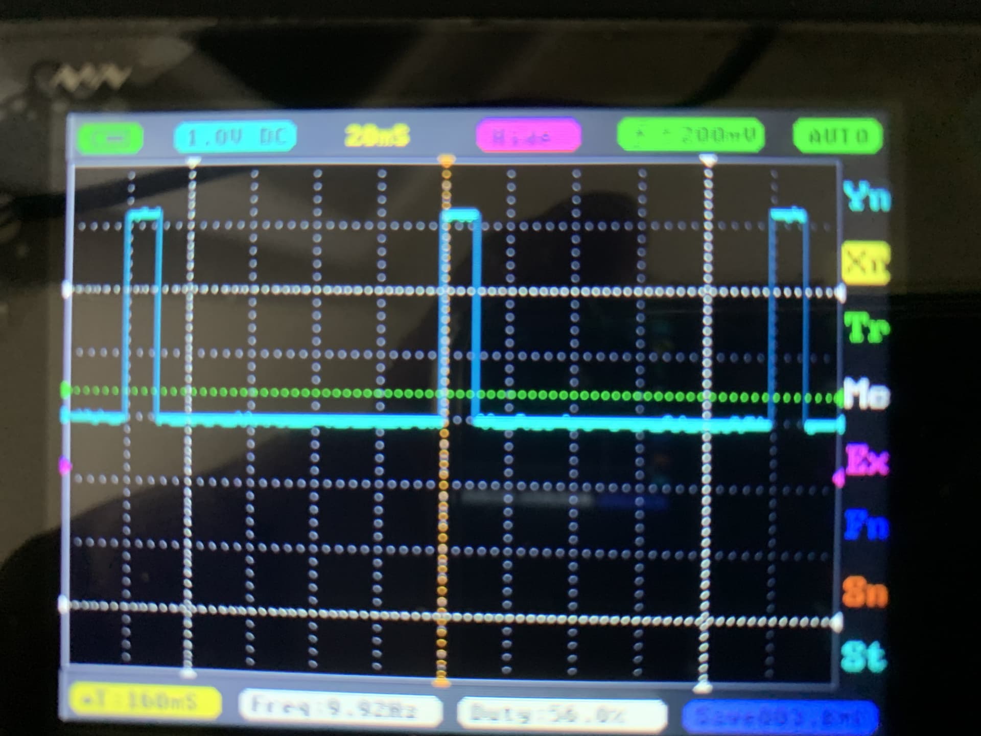
See attached pictures of fan running at 40% duty cycle.

Uploading: P1030724.JPG...

1 Like

Hi @khoih-prog

I’m having trouble using this with the following setup and sketch.

When the PWM is set to deliver 0 % dutycycle, it is instead delivering
something that looks like 10% (first clip). When PWM is set to deliver 50 % dutycycle, it is delivering something that looks like 60 % (second clip).
Measured with the analogread it looks like this:


My HW:

Seeed BLE (nRF52840) Getting Started with XIAO BLE (Sense) - Seeed Wiki (seeedstudio.com)

Pololu #2135 (DRV8835) https://www.pololu.com/product/2135

And micro gearmotor

#include <nRF52_MBED_Slow_PWM.h>

#define LED_Blue LEDB
#define LED_Green LEDG
#define LED_Red LEDR

#define MOTORA_ENABLE 10 
#define MOTORA_PHASE 2 
//#define MOTORB_ENABLE 1 
//#define MOTORB_PHASE 0 

// motor, PWM
#define _PWM_LOGLEVEL_       1
#define USING_MICROS_RESOLUTION       false    // true 
#define HW_TIMER_INTERVAL_US      20L
volatile uint32_t startMillis = 0; // 
// Init NRF52 timer NRF_TIMER3
NRF52_MBED_Timer ITimer(NRF_TIMER_3);

// Init nRF52_Slow_PWM, each can service 16 different ISR-based PWM channels
NRF52_MBED_Slow_PWM ISR_PWM;

int PWMchannelMotorA;
int PWMchannelMotorB; 

void TimerHandler()
{ 
  ISR_PWM.run();
}


void setup() {
  // put your setup code here, to run once:
  Serial.begin(115200);  // 
    
  Serial.println("setup start");
  
  // LED
  pinMode(LED_Blue, OUTPUT);
  pinMode(LED_Green, OUTPUT);
  pinMode(LED_Red, OUTPUT);
  digitalWrite(LED_Blue, HIGH);
  digitalWrite(LED_Green, HIGH);
  digitalWrite(LED_Red, LOW);

  pinMode(MOTORA_PHASE, OUTPUT); 
  //pinMode(MOTORB_PHASE, OUTPUT); 
  pinMode(MOTORA_ENABLE, OUTPUT); 
  //pinMode(MOTORB_ENABLE, OUTPUT); 

  // setup motors
  //  Interval in millis
  if (ITimer.attachInterruptInterval(HW_TIMER_INTERVAL_US, TimerHandler))
  {
    //startMicros = micros(); 
    startMillis = millis(); 
    Serial.print(F("Starting ITimer OK, micros() = ")); Serial.println(startMillis);
  }
  else
    Serial.println(F("Can't set ITimer. Select another freq. or timer"));

  PWMchannelMotorA= ISR_PWM.setPWM(MOTORA_ENABLE, 100.0, 50.0); // pinno., fre, dutycycle
  //PWMchannelMotorB= ISR_PWM.setPWM(MOTORB_ENABLE, 100.0, 0.0); // pinno., fre, dutycycle
  
  digitalWrite(MOTORA_PHASE, LOW);
  //digitalWrite(MOTORB_PHASE, LOW);
    
  analogReadResolution(10);

  digitalWrite(LED_Green, LOW);
  digitalWrite(LED_Red, HIGH);
  
  Serial.println("setup end");

}


void loop() {
  // put your main code here, to run repeatedly:

  
          delay(1000);
          ISR_PWM.modifyPWMChannel(PWMchannelMotorA, MOTORA_ENABLE, 100.0, 50.0); // 0.0
          while (1) {
            Serial.println(analogRead(1));
          }
          
}

Hi,

The nRF52_MBED_Slow_PWM library is written and tested for Nano_33_BLE

You're on your own to use with untested and unsupported Seeed XIAO BLE board as I don't have that same board to test.

Also, use the oscilloscope or logic analyser to correctly measure the PWM pulse, not by using your code in the loop()

Good Luck,

This topic was automatically closed 180 days after the last reply. New replies are no longer allowed.