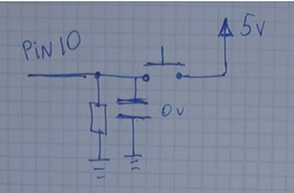
Where would I place a capacitor and/or other components to hardware debounce this setup?

I can't see the image...
Here is a link to it...Images/Analog.png at master · j-bellavance/Images · GitHub
One would think that a link to an image [\img] would hold an image...
Hey, Larry, How did you do that???
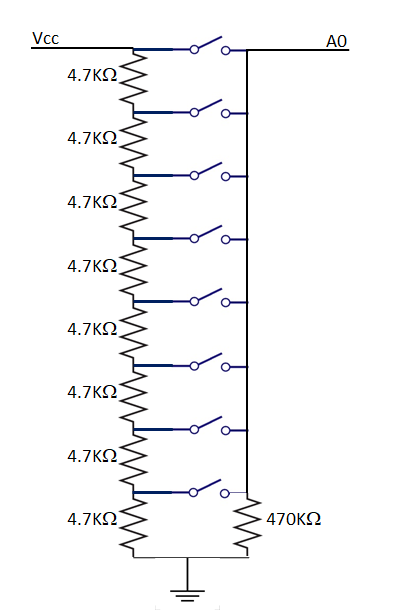
Why 470K ?
Also, read the analog input twice, use the second reading.
That would be software debounce. How about hardware debounce?
Actually, it helps the analog input settle down.
For input stability, place a 100nF capacitor from A0 to GND.
.
Why 470K ?
I tried first with another 4.7K and the readings were not as close to the values I wanted, so I increased the resistor to 47K and the results got closer. Finally, at 470K, the results are close enough to what I want.
I still have to do the math to clearly know why it works though ![]() .
.
Jacques
For input stability, place a 100nF capacitor from A0 to GND.
Thanks and Seasons Greetings to you too.
This is what I found, R being 10K (standard pull down resistor) and the capacitor 10nF. But how higher the capacitance the longer the "debounce effect" since the capacitor discharges itself over the in this case 10K resistor, so I do agree with 100nF.
I hope the image link works, it would be the first time for me. Here is a link to the Image.
Thank you Sir
Ok, I did the maths.
Voltage at A0 depends on which switch is pressed. Say R1 is the sum of all resistors above the switch that is pressed and R2 the sum of all resistors below the switch that is pressed.
Then Voltage at A0 = 5 * R2 / (R1 - R2).
Everyting is fine, and the setup behaves just like an ordinary potentiometer. But...
Now we can have the possibility that no switch is pressed. To avoid having A0 to "float", let's link it to ground via a resistor (R3).
Now R3 is parallel to R2 and old R2 becomes (R2*R3)/(R2+R3). To keep the new R2 as close to the original R2, we need (ideally) to have R3 = to be infinite.
So, here is where 470K comes from. 100 times 4.7K looks cool and is high enough to keep new R2 close enough to old R2 so that the system still behaves like a potentiometer with 0V when no switch is pressed.
Oops, I only just got what you where trying to do, please except my apologies.
No need to apologize.
I was not clear that I was responding to Larry's question.
Reminds me of an R2R ladder network.
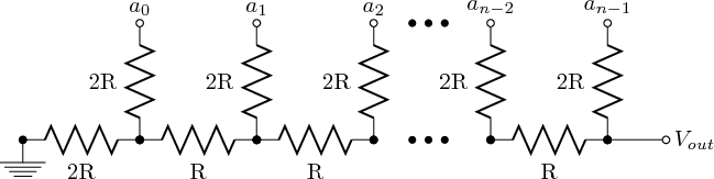
Reminds me of an R2R ladder network.
Lucky for me, analogRead(A0) takes care of the Analog to Digital part of the workload. ![]() It saves me some resistors.
It saves me some resistors.