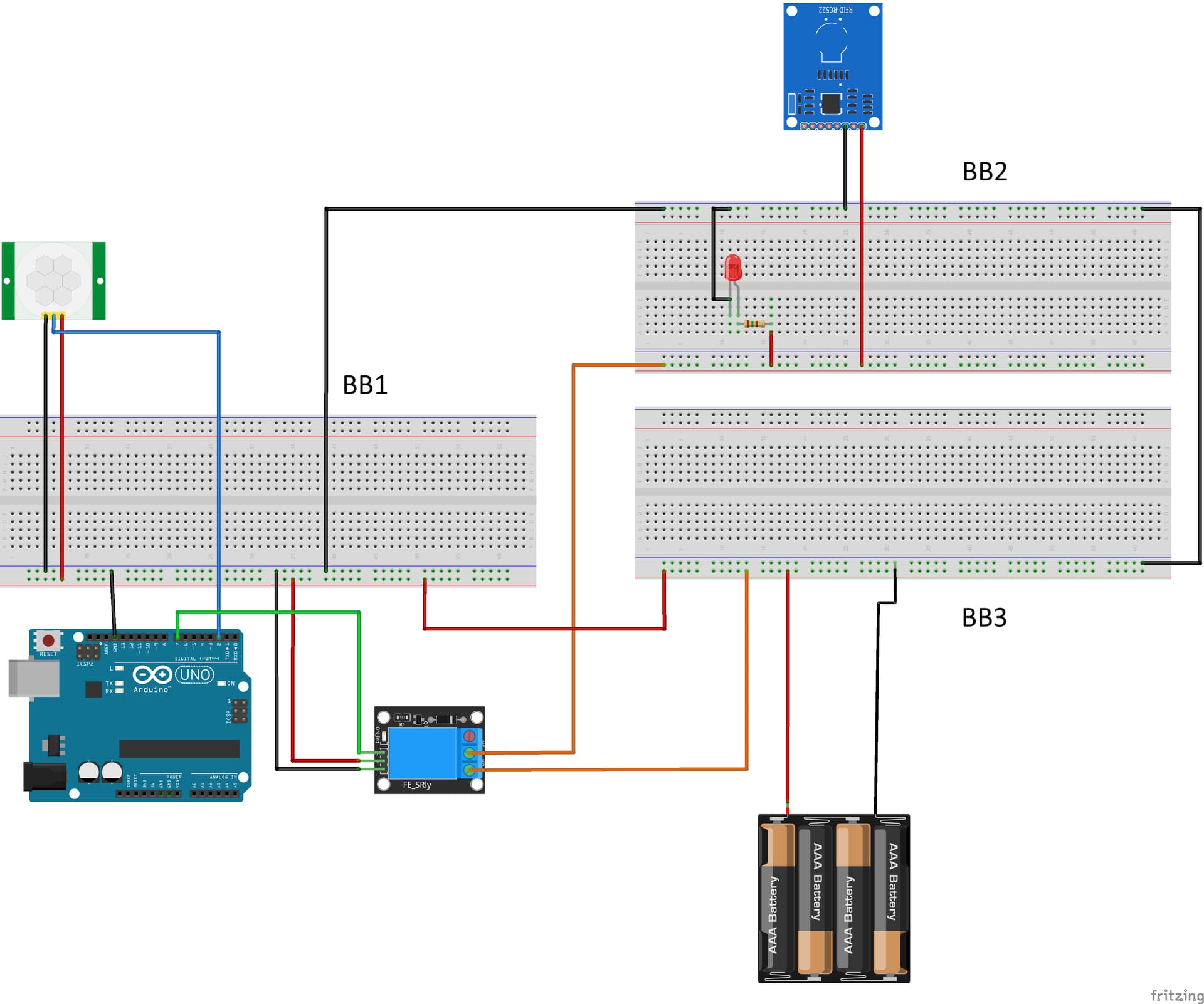
This is the setup with essentially the minimal components (and no wires from the rfid reader). The batteries here are actually a 5V PSU. What I am finding is that sharing a common ground with the Ardunio, appears to cause the relay indicator light to be always on, and the motion sensor to always misread the signal.
BB1 is meant to be my "always on" power rail, BB2 is "sometimes on", for when I want the rfid to begin scanning, and BB3 is the splitter. Bridging them and having a "common ground", seems to be causing backfeeding.
I have tried this setup in a variety of ways but am finding it difficult to isolate modules. What ALMOST works is running the relay and motion sensor entirely off the arduino 5V and keeping the 5V PSU passing only through the relay. I say almost because that still seems to have read issues with the RFID.
Is it possible to isolate a module from the arduino power circuit and still have it communicate with signal wires effectively?
This is probably a simple solution but my experience with electronics is low.
Perhaps I am missing something, but I don;t see any power going to the UNO. Based on your comments, you say you are powering components from the UNO? NEVER do that.
Hey sorry, this is just a diagram of my real life model. In that, I have the USB plugged in to my arduino, OR dedicated 9V PSU.
What do you mean NEVER power components from the arduino? For what reason does it have the 5v or 3.3v output and grounds?
Well, yes, you can power very low-power sensors like temperature or humidity as long as it is less than 20mA. The 3.3v pin can go as high as 50mA, but anything like a servo, motor, relay, etc, needs a separate PSU.
Your problem is it appears as if the relay is miswired. I don't see any control circuit.
When you say "control circuit", is that how I should be powering all modules? Would you be able to link or share a diagram that shows this in a very basic way that I can expand upon to multiple modules?
I was only talking about the relay, assuming that it is a relay.
Your entire diagram appears 'different'. It may be fine, but that is one old mans impression. Perhaps if you could explain what it is you want to do WITHOUT suggesting a solution, the volunteers could comment better.
A quick look and a read of your post tells me you want the PIR to be always on and the RFID to only come on after the PIR detects something.
Is that close?
That's exactly correct. The PIR (powered by PSU) should be always scanning, and when it detects motions it tells the arduino to set the Relay(also powered by PSU) pin to high, so that the PSU power will pass thru the relay NO channel and power BB2, to activate my RFID reader, and any other modules I only want turned on following a motion detection.
The issue seems to be with how the wiring is arranged.
Assuming my Arduino has power, and my PSU is a steady 5v, and my code is correct, how would I adjust my wiring to achieve this?
Currently, the relay indicator light is always on, and my PIR is giving false positives to my serial monitor. I'm not convinced the relay is closed tho, because my power indicator LED on BB2 is not lighting up.
And when I power the vcc and gnd to the PIR and relay from the arduino 5V, isolating the arudino 5v from the PSU 5v, it behaves exactly as desired.
For the life of me, I don't know what I did, but I took it apart and re-assembled exactly as you see the diagram here and it is working as intended. I don't understand but maybe I overlooked something. I apologize for that.
I suppose my question is now, can I freely add more modules to the PSU load on BB2 or are there special considerations when having multiple modules on the common ground?
Sometimes you get lucky.
Do you know where the THREE (3) contacts are labelled C NC and NO, which stand for Common, Normally Closed, and Normally Open? That is where the LOAD will go, which in your case is the 5V power to the BB2, as you call it. If the relay is a modern type with opto couplers and a logic level voltage input, then there will be TWO (2) connections on the other side. It is those two that the code will control, so one connector will go to Ground, and the other to a pin on the Arduio. In your code you make that pin an OUTPUT pin. When you get the PIR signal, you write HIGH to that pin.
Is that enough?
I believe that's how I have it now. Previously, for whatever reason, maybe just an oversight, it didn't seem to function correctly. But as it is diagramed is how it is working now.
The relay is the KY-019. It has a NO, NC, COM, GND, VCC, and Signal. I'm not sure if it has opto couplers. If it does, does that isolate everything on the other side of the NO/COM (Breadboard 2)?
From a scalability standpoint, is there more I should add to this circuit to ensure more modules can be added without complications?
Would it be alright if I check back in as I attach some more modules if I encounter any electrical surprises?