Hello World will not display on MSP807 display when Driven by ESP32 module

I am learning how to interface an MSP2807 SPI TFT display, driven by the ILI9341IC on the backside of the display PCB. I am driving this display with a 30-pin DOIT ESP32 DEVKIT V1 module. The attached Hello World sketch is taken from the Arduino GFX Library.
The sketch compiles and uploads with no problem to the ESP32 module. It will not display the"Hello World" text on the MSP2807 display. I have checked both the display and the ESP32 module to see if they work OK. They do.

What am I doing wrong? The code for the sketch is shown below

/*******************************************************************************
 * Start of Arduino_GFX setting
 * 
 * Arduino_GFX try to find the settings depends on selected board in Arduino IDE
 * Or you can define the display dev kit not in the board list
 * Defalult pin list for non display dev kit:
 * Arduino Nano, Micro and more: TFT_CS:  9, TFT_DC:  8, TFT_RST:  7, TFT_BL:  6
 * ESP32 various dev board     : TFT_CS:  5, TFT_DC: 27, TFT_RST: 33, TFT_BL: 22
 * ESP8266 various dev board   : TFT_CS: 15, TFT_DC:  4, TFT_RST:  2, TFT_BL:  5
 * Raspberry Pi Pico dev board : TFT_CS: 17, TFT_DC: 27, TFT_RST: 26, TFT_BL: 28
 * RTL872x various dev board   : TFT_CS: 18, TFT_DC: 17, TFT_RST:  2, TFT_BL: 23 
 * Seeeduino XIAO dev board    : TFT_CS:  3, TFT_DC:  2, TFT_RST:  1, TFT_BL:  0
 * Teensy 4.1 dev board        : TFT_CS: 39, TFT_DC: 41, TFT_RST: 40, TFT_BL: 22
 ******************************************************************************/
#include <Arduino_GFX_Library.h>

//  ##############################################################################
//  ##############################################################################
//  #
//  #   Pin Setups for ESP32 Dev Board   
//  #
//  ############################################################################## 
//  ############################################################################## 

//  ESP32 various dev board     : TFT_CS:  5, TFT_DC: 27, TFT_RST: 33, TFT_BL: 22

  
     #define TFT_CS     5  //  CS   - 3 - Brown 
     #define TFT_RST   33  //  RST  - 4 - Red   
     #define TFT_DC    27  //  DC   - 5 - Orange
     #define TFT_LED   22  //  LED  - 8 - Blue
       
/* More dev device declaration: https://github.com/moononournation/Arduino_GFX/wiki/Dev-Device-Declaration */

#if defined(DISPLAY_DEV_KIT)
Arduino_GFX *gfx = create_default_Arduino_GFX();
#else /* !defined(DISPLAY_DEV_KIT) */

/* More data bus class: https://github.com/moononournation/Arduino_GFX/wiki/Data-Bus-Class */

Arduino_DataBus *bus = create_default_Arduino_DataBus();

/* More display class: https://github.com/moononournation/Arduino_GFX/wiki/Display-Class */

Arduino_GFX *gfx = new Arduino_ILI9341(bus, TFT_RST, 0 /* rotation */, false /* IPS */);

#endif /* !defined(DISPLAY_DEV_KIT) */

/*******************************************************************************
 * End of Arduino_GFX setting
 ******************************************************************************/

void setup(void)
{
    gfx->begin();
    gfx->fillScreen(BLACK);

#ifdef TFT_BL
    pinMode(TFT_BL, OUTPUT);
    digitalWrite(TFT_BL, HIGH);
#endif

    gfx->setCursor(10, 10);
    gfx->setTextColor(RED);
    gfx->println("Hello World!");

    delay(5000); // 5 seconds
}

void loop()
{
    gfx->setCursor(random(gfx->width()), random(gfx->height()));
    gfx->setTextColor(random(0xffff), random(0xffff));
    gfx->setTextSize(random(6) /* x scale */, random(6) /* y scale */, random(2) /* pixel_margin */);
    gfx->println("Hello World!");

    delay(1000); // 1 second
}

The ESP32 has 2 I/O ports. The first 32 I/O ports are on portA and the rest of the pins are on portB. PortB is optimized for A:D inputs. portB GPIO are input only.

I changed the TFT_RST pin to TFT_RST 25. The sketch still does not work.

After you've made a code change, please post the new code.

Does the BL illuminate?

No, the BL does not illuminate. Question, when you refer to a pin on the esp32 module as
Pin 5, do you attach the wire from the MSP2807 display to the module's Pin 5, or to Pin D5 on the module?

/*******************************************************************************
 * Start of Arduino_GFX setting
 * 
 * Arduino_GFX try to find the settings depends on selected board in Arduino IDE
 * Or you can define the display dev kit not in the board list
 * Defalult pin list for non display dev kit:
 * Arduino Nano, Micro and more: TFT_CS:  9, TFT_DC:  8, TFT_RST:  7, TFT_BL:  6
 * ESP32 various dev board     : TFT_CS:  5, TFT_DC: 27, TFT_RST: 33, TFT_BL: 22
 * ESP8266 various dev board   : TFT_CS: 15, TFT_DC:  4, TFT_RST:  2, TFT_BL:  5
 * Raspberry Pi Pico dev board : TFT_CS: 17, TFT_DC: 27, TFT_RST: 26, TFT_BL: 28
 * RTL872x various dev board   : TFT_CS: 18, TFT_DC: 17, TFT_RST:  2, TFT_BL: 23 
 * Seeeduino XIAO dev board    : TFT_CS:  3, TFT_DC:  2, TFT_RST:  1, TFT_BL:  0
 * Teensy 4.1 dev board        : TFT_CS: 39, TFT_DC: 41, TFT_RST: 40, TFT_BL: 22
 ******************************************************************************/
#include <Arduino_GFX_Library.h>

//  ##############################################################################
//  ##############################################################################
//  #
//  #   Pin Setups for ESP32 Dev Board   
//  #
//  ############################################################################## 
//  ############################################################################## 

//  ESP32 various dev board     : TFT_CS:  5, TFT_DC: 27, TFT_RST: 33, TFT_BL: 22

  
     #define TFT_CS     5  //  CS   - 3 - Brown 
     #define TFT_RST   25  //  RST  - 4 - Red   made change from pin 33 to pin 30
     #define TFT_DC    27  //  DC   - 5 - Orange
     #define TFT_BL    22  //  LED  - 8 - Blue
       
/* More dev device declaration: https://github.com/moononournation/Arduino_GFX/wiki/Dev-Device-Declaration */

#if defined(DISPLAY_DEV_KIT)
Arduino_GFX *gfx = create_default_Arduino_GFX();
#else /* !defined(DISPLAY_DEV_KIT) */

/* More data bus class: https://github.com/moononournation/Arduino_GFX/wiki/Data-Bus-Class */

Arduino_DataBus *bus = create_default_Arduino_DataBus();

/* More display class: https://github.com/moononournation/Arduino_GFX/wiki/Display-Class */

Arduino_GFX *gfx = new Arduino_ILI9341(bus, TFT_RST, 0 /* rotation */, false /* IPS */);

#endif /* !defined(DISPLAY_DEV_KIT) */

/*******************************************************************************
 * End of Arduino_GFX setting
 ******************************************************************************/

void setup(void)
{
    gfx->begin();
    gfx->fillScreen(BLACK);

#ifdef TFT_BL
    pinMode(TFT_BL, OUTPUT);
    digitalWrite(TFT_BL, HIGH);
#endif

    gfx->setCursor(10, 10);
    gfx->setTextColor(RED);
    gfx->println("Hello World!");

    delay(5000); // 5 seconds
}

void loop()
{
    gfx->setCursor(random(gfx->width()), random(gfx->height()));
    gfx->setTextColor(random(0xffff), random(0xffff));
    gfx->setTextSize(random(6) /* x scale */, random(6) /* y scale */, random(2) /* pixel_margin */);
    gfx->println("Hello World!");

    delay(1000); // 1 second
}

the most secure way to define IO-pins is using the GPIO-numbers directly as a decimal GPIO-
number. Sometimes the IO-pin-names like "D5" are not the same as the GPO-number one example is the WeMos D1 mini board. Though for the ESP32 DEV Kit the numbers seems to be the same.

This picture shows the Pinout

With ESP8266 and ESP32 with some displays I had a hard time to find out the correct connections that work.
As you can see from the Pin-out an ESP32 has two SPI-buses VSPI and HSPI.

The initialisation of the display in your code does not show which GPIO-pins are really used for the SPI-interface as there are:

  • MISO
  • MOSI
  • SCK
    I would check in the library-files which GPIO-pins does the library really use

How did you check the display to work OK?
For this checking if it was a real checking that the pixels of the display show a senseful pattern you must have used some testcode.
How does this testcode look like? Please post the testcode.
What is the wiring that this testcode needs?

As this testcode works does the testcode offer graphic features?
What is the purpose for using this display?
If you give an overview about your project the users here are able to make suggestions how displaying these things can be done.

best regards Stefan

I looked up the typenumber you have written in the title

MSP807

and found ..... nothing.
you made a typo that fooled me. The name of the display is

MSP2807

and the more important information is the type-number of the display-driver-chip
which is:

ILI9341

You should post a link to where you bought the display from.
There are so many different display-driver-chips on the market that we should make really sure what type of driver-chip is on your display

The first thing I do if I came across a new device is googling with this keywords

"GitHub" "Arduino" - "driverchip-number"
so in your case

or adding the board-type

To find demo-codes for the device.
Then I look them through which demo-code is easy to understand to be able to customise the demo-code

Edit:
This one looks promising to me as it has a demo-code that shows a lot of different things like
showing lines, rectangles triangles circles etc. on the screen

The initialisation code clearly names the used IO-pins

// For the ESP-WROVER_KIT, these are the default.
#define TFT_CS   22
#define TFT_DC   21
#define TFT_MOSI 23
#define TFT_CLK  19
#define TFT_RST  18
#define TFT_MISO 25
#define TFT_LED   5  // GPIO not managed by library

Adafruit_ILI9341 tft = Adafruit_ILI9341(TFT_CS, TFT_DC, TFT_MOSI, TFT_CLK, TFT_RST, TFT_MISO);

IMHO this is the best way to make code easy to understand.
naming all used IO-pins in the initialisation. The library you use hides the IO-pins away in the library-file.

After comparing the used IO-pin-numbers I think

strange configuration

it does not use the standard definitions like shown in the pinout
so maybe this one is better suited

because the used IO-pin-numbers are the ones named in the pin-out
In this special case I use a picture instead of a code-section to make it easier to see
the relations

best regards Stefan

I use GPIO_NUM_1, or GPIO_NUM_X to represent the ESP32's GPIO pins not PIN numbers of the chip.

If the BL does not illuminate then the display will not show thingies. Put the BL pin to 3.3V. Does the BL illuminate?

 gpio_config_t io_cfg = {}; // initialize the gpio configuration structure
  io_cfg.mode = GPIO_MODE_OUTPUT; // set gpio mode
  io_cfg.pin_bit_mask = ( (1ULL << GPIO_NUM_4) ); //bit mask of the pins to set
  gpio_config(&io_cfg); // configure the gpio based upon the parameters as set in the configuration structure
  gpio_set_level( GPIO_NUM_4, LOW); // set air particle sensor trigger pin to LOW
  // input mode
  io_cfg = {}; // reinitialize the gpio configuration structure
  io_cfg.mode = GPIO_MODE_INPUT; // set gpio mode. GPIO_NUM_0 input from water level sensor
  io_cfg.pin_bit_mask = ( (1ULL << GPIO_NUM_0) | (1ULL << GPIO_NUM_27)  ); //bit mask of the pins to set, assign gpio number to be configured

Yes. When I connect the BL pin to 3.3V, the BL illuminates.

Once the BL is illuminated, leaving the BL to 3.3V, reset the unit, does it display the hello world thingy. If not time to post images of your project.

With the BL illuminated, I reset the unit. There was no "Hello World" display. Sorry for the delay in back to you. I was waiting for the delivery of a new MSP2807 display. I plugged this new display into my bread board circuit and loaded the sketch into the ESP32 module. There was still no display of "Hello World.

Test Setup and Photos
I am using the bread board circuit board from the Fritzing PCB design application. I placed a female socket header with 1/2" long headers onto this circuit board. Then I plugged my MSP2807 display into this header.

I connect to the display labeled connector pins with wires plugged into the circuit board which line up with the desired MSP2307 display connector pin. I have a different colored wire connecting each labeled display pin to the desired ESP32 module pin #.

I use four wires to connect the MSP 2807 display to the ESP32 module.

Brown wire connects CS on the display to GPIO5 - D5 on the ESP32 module
Yellow wire connects RESET on the display to GPIO25 - D25 on the ESP32 module
Orange wire connects DC on the display to GPIO27 - D27 on the ESP32 module
Blue wire connects LED on the display to GPIO22 - D22 on the ESP32 module

These wires are shown in the photos.


This photo shows the overall test fixture

This photo shows connections to GPIO 5, GPIO21, and GPIO22 from the display. The wires in the lower RH corner are for 3V3 and GND from the ESP32 module.

This photo shows the connection GPIO25 from the display. This photo also shows connections to GPIO 5, GPIO21, and GPIO22 from the display.

This photo shows all of the wires from the display connected to the ESP32 module. I was able to take this shot with good focus.

Updated Sketch

The latest file for this sketch is shown below. With this submission, I hope that you can see what I am doing wrong.

 
 * ESP32 various dev board     : TFT_CS:  5, TFT_DC: 27, TFT_RST: 33, TFT_BL: 22
 
 ******************************************************************************/
#include <Arduino_GFX_Library.h>

//  ##############################################################################
//  ##############################################################################
//  #
//  #      Pin Setups for ESP32 Dev Board   
//  #
//  ############################################################################## 
//  ############################################################################## 

//  ESP32 various dev board     : TFT_CS:  5, TFT_DC: 27, TFT_RST: 33, TFT_BL: 22

//                                   ESP32             Display       BB  
//                             Pin   GPIOX   Pin         Pin      Wire
//                              #     #     Label       Label    Color
     #define TFT_CS     5  //  5  - GPIO5    D5    to    CS      Brown 
     #define TFT_RST   25  //  25 - GPIO25   D25   to    RST     Yellow   
     #define TFT_DC    27  //  27 - GPIO27   D27   to    DC      Orange
     #define TFT_LED   22  //  22 - GPIO22   D22   to    LED     Blue
       
/* More dev device declaration: https://github.com/moononournation/Arduino_GFX/wiki/Dev-Device-Declaration */

#if defined(DISPLAY_DEV_KIT)
Arduino_GFX *gfx = create_default_Arduino_GFX();
#else /* !defined(DISPLAY_DEV_KIT) */ 

/* More data bus class: https://github.com/moononournation/Arduino_GFX/wiki/Data-Bus-Class */

Arduino_DataBus *bus = create_default_Arduino_DataBus();

/* More display class: https://github.com/moononournation/Arduino_GFX/wiki/Display-Class */

Arduino_GFX *gfx = new Arduino_ILI9341(bus, TFT_RST, 0 /* rotation */, false /* IPS */);

#endif /* !defined(DISPLAY_DEV_KIT) */

/*******************************************************************************
 * End of Arduino_GFX setting
 ******************************************************************************/

void setup(void)
{
    gfx->begin();
    gfx->fillScreen(BLACK);

#ifdef TFT_BL
    pinMode(TFT_BL, OUTPUT);
    digitalWrite(TFT_BL, HIGH);
#endif

    gfx->setCursor(10, 10);
    gfx->setTextColor(RED);
    gfx->println("Hello World!");

    delay(5000); // 5 seconds
}

void loop()
{
    gfx->setCursor(random(gfx->width()), random(gfx->height()));
    gfx->setTextColor(random(0xffff), random(0xffff));
    gfx->setTextSize(random(6) /* x scale */, random(6) /* y scale */, random(2) /* pixel_margin */);
    gfx->println("Hello World!");

    delay(1000); // 1 second
}

I did not see the backlight light illuminated.

Also, many breadboards have a split of the power rails in the center. Have you used a multi-meter to measure if the volts are reaching the display?

I didn't have power on the ESP32 when I shot the photos.

I hooked BL up to 3.3V and the BL came on. Then I uploaded the sketch and "Hello World" did not show up on the screen.

Hi grenken,

would mind testing with a

different

demo-sketch?
which as a

different wiring

?
I mean this sketch


#include "Arduino.h"
#include "SPI.h"
#include "tft.h"

#define TFT_DC   21    /* Data or Command */
#define TFT_CS   22    /* SPI Chip select */
#define TFT_BL   17    /* BackLight */
#define TFT_SCK  18
#define TFT_MISO 19
#define TFT_MOSI 23
#define TFT_RST  16    /* Reset */
#define TP_IRQ   39
#define TP_CS    16
#define SD_CS     5

#define min(X, Y) (((X) < (Y)) ? (X) : (Y))

TFT tft(0); //0=ILI9341, 1= HX8347D

void setup() {
  pinMode(TP_CS, OUTPUT);
  digitalWrite(TP_CS, HIGH); // disable touchpad
  pinMode(SD_CS, OUTPUT);
  digitalWrite(SD_CS, HIGH); // disable SDcard
  
  Serial.begin(115200);

  //tft.begin(); //default (21,22,17,18,19,23,16)
  tft.begin(TFT_CS, TFT_DC, TFT_MOSI, TFT_MISO, TFT_SCK, TFT_BL);
  tft.setRotation(1);

  Serial.println(F("Benchmark                Time (microseconds)"));
  delay(10);
  Serial.print(F("Screen fill              "));
  Serial.println(testFillScreen());
  delay(500);

  Serial.print(F("Text                     "));
  Serial.println(testText());
  delay(3000);

  Serial.print(F("Lines                    "));
  Serial.println(testLines(TFT_CYAN));
  delay(500);

  Serial.print(F("Horiz/Vert Lines         "));
  Serial.println(testFastLines(TFT_RED, TFT_BLUE));
  delay(500);

  Serial.print(F("Rectangles (outline)     "));
  Serial.println(testRects(TFT_GREEN));
  delay(500);

  Serial.print(F("Rectangles (filled)      "));
  Serial.println(testFilledRects(TFT_YELLOW, TFT_MAGENTA));
  delay(500);

  Serial.print(F("Circles (filled)         "));
  Serial.println(testFilledCircles(10, TFT_MAGENTA));

  Serial.print(F("Circles (outline)        "));
  Serial.println(testCircles(10, TFT_WHITE));
  delay(500);

  Serial.print(F("Triangles (outline)      "));
  Serial.println(testTriangles());
  delay(500);

  Serial.print(F("Triangles (filled)       "));
  Serial.println(testFilledTriangles());
  delay(500);

  Serial.print(F("Rounded rects (outline)  "));
  Serial.println(testRoundRects());
  delay(500);

  Serial.print(F("Rounded rects (filled)   "));
  Serial.println(testFilledRoundRects());
  delay(500);

  Serial.println(F("Done!"));

  delay(5000);
  printf("ESP32: RAM left %d\n",  esp_get_free_heap_size());
}

void loop(void) {
  for(uint8_t rotation=0; rotation<4; rotation++) {
    tft.setRotation(rotation);
    testText();
    delay(2000);
  }
}

unsigned long testFillScreen() {
  unsigned long start = micros();
  tft.fillScreen(TFT_BLACK);
  yield();
  tft.fillScreen(TFT_RED);
  yield();
  tft.fillScreen(TFT_GREEN);
  yield();
  tft.fillScreen(TFT_BLUE);
  yield();
  tft.fillScreen(TFT_BLACK);
  yield();
  return micros() - start;
}

unsigned long testText() {
  tft.fillScreen(TFT_BLACK);
  unsigned long start = micros();
  tft.setCursor(0, 0);
  tft.setTextColor(TFT_WHITE);  tft.setTextSize(1);
  tft.println("Hello World!");
  tft.setTextColor(TFT_YELLOW); tft.setTextSize(2);
  tft.println(1234.56);
  tft.setTextColor(TFT_RED);    tft.setTextSize(3);
  tft.println(0xDEADBEEF, HEX);
  tft.println();
  tft.setTextColor(TFT_GREEN);
  tft.setTextSize(6);
  tft.println("Groop");
  tft.setTextSize(2);
  tft.println("I implore thee,");
  tft.setTextSize(1);
  tft.println("my foonting turlingdromes.");
  tft.println("And hooptiously drangle me");
  tft.println("with crinkly bindlewurdles,");
  tft.println("Or I will rend thee");
  tft.println("in the gobberwarts");
  tft.println("with my blurglecruncheon,");
  tft.println("see if I don't!");
  return micros() - start;
}

unsigned long testLines(uint16_t color) {
  unsigned long start, t;
  int           x1, y1, x2, y2,
                w = tft.width(),
                h = tft.height();

  tft.fillScreen(TFT_BLACK);
  yield();

  x1 = y1 = 0;
  y2    = h - 1;
  start = micros();
  for(x2=0; x2<w; x2+=6) tft.drawLine(x1, y1, x2, y2, color);
  x2    = w - 1;
  for(y2=0; y2<h; y2+=6) tft.drawLine(x1, y1, x2, y2, color);
  t     = micros() - start; // fillScreen doesn't count against timing

  yield();
  tft.fillScreen(TFT_BLACK);
  yield();

  x1    = w - 1;
  y1    = 0;
  y2    = h - 1;
  start = micros();
  for(x2=0; x2<w; x2+=6) tft.drawLine(x1, y1, x2, y2, color);
  x2    = 0;
  for(y2=0; y2<h; y2+=6) tft.drawLine(x1, y1, x2, y2, color);
  t    += micros() - start;

  yield();
  tft.fillScreen(TFT_BLACK);
  yield();

  x1    = 0;
  y1    = h - 1;
  y2    = 0;
  start = micros();
  for(x2=0; x2<w; x2+=6) tft.drawLine(x1, y1, x2, y2, color);
  x2    = w - 1;
  for(y2=0; y2<h; y2+=6) tft.drawLine(x1, y1, x2, y2, color);
  t    += micros() - start;

  yield();
  tft.fillScreen(TFT_BLACK);
  yield();

  x1    = w - 1;
  y1    = h - 1;
  y2    = 0;
  start = micros();
  for(x2=0; x2<w; x2+=6) tft.drawLine(x1, y1, x2, y2, color);
  x2    = 0;
  for(y2=0; y2<h; y2+=6) tft.drawLine(x1, y1, x2, y2, color);

  yield();
  return micros() - start;
}

unsigned long testFastLines(uint16_t color1, uint16_t color2) {
  unsigned long start;
  int           x, y, w = tft.width(), h = tft.height();

  tft.fillScreen(TFT_BLACK);
  start = micros();
  for(y=0; y<h; y+=5) tft.drawFastHLine(0, y, w, color1);
  for(x=0; x<w; x+=5) tft.drawFastVLine(x, 0, h, color2);

  return micros() - start;
}

unsigned long testRects(uint16_t color) {
  unsigned long start;
  int           n, i, i2,
                cx = tft.width()  / 2,
                cy = tft.height() / 2;

  tft.fillScreen(TFT_BLACK);
  n     = min(tft.width(), tft.height());
  start = micros();
  for(i=2; i<n; i+=6) {
    i2 = i / 2;
    tft.drawRect(cx-i2, cy-i2, i, i, color);
  }

  return micros() - start;
}

unsigned long testFilledRects(uint16_t color1, uint16_t color2) {
  unsigned long start, t = 0;
  int           n, i, i2,
                cx = tft.width()  / 2 - 1,
                cy = tft.height() / 2 - 1;

  tft.fillScreen(TFT_BLACK);
  n = min(tft.width(), tft.height());
  for(i=n; i>0; i-=6) {
    i2    = i / 2;
    start = micros();
    tft.fillRect(cx-i2, cy-i2, i, i, color1);
    t    += micros() - start;
    // Outlines are not included in timing results
    tft.drawRect(cx-i2, cy-i2, i, i, color2);
    yield();
  }

  return t;
}

unsigned long testFilledCircles(uint8_t radius, uint16_t color) {
  unsigned long start;
  int x, y, w = tft.width(), h = tft.height(), r2 = radius * 2;

  tft.fillScreen(TFT_BLACK);
  start = micros();
  for(x=radius; x<w; x+=r2) {
    for(y=radius; y<h; y+=r2) {
      tft.fillCircle(x, y, radius, color);
    }
  }

  return micros() - start;
}

unsigned long testCircles(uint8_t radius, uint16_t color) {
  unsigned long start;
  int           x, y, r2 = radius * 2,
                w = tft.width()  + radius,
                h = tft.height() + radius;

  // Screen is not cleared for this one -- this is
  // intentional and does not affect the reported time.
  start = micros();
  for(x=0; x<w; x+=r2) {
    for(y=0; y<h; y+=r2) {
      tft.drawCircle(x, y, radius, color);
    }
  }

  return micros() - start;
}

unsigned long testTriangles() {
  unsigned long start;
  int           n, i, cx = tft.width()  / 2 - 1,
                      cy = tft.height() / 2 - 1;

  tft.fillScreen(TFT_BLACK);
  n     = min(cx, cy);
  start = micros();
  for(i=0; i<n; i+=5) {
    tft.drawTriangle(
      cx    , cy - i, // peak
      cx - i, cy + i, // bottom left
      cx + i, cy + i, // bottom right
      tft.color565(i, i, i));
  }

  return micros() - start;
}

unsigned long testFilledTriangles() {
  unsigned long start, t = 0;
  int           i, cx = tft.width()  / 2 - 1,
                   cy = tft.height() / 2 - 1;

  tft.fillScreen(TFT_BLACK);
  start = micros();
  for(i=min(cx,cy); i>10; i-=5) {
    start = micros();
    tft.fillTriangle(cx, cy - i, cx - i, cy + i, cx + i, cy + i,
      tft.color565(0, i*10, i*10));
    t += micros() - start;
    tft.drawTriangle(cx, cy - i, cx - i, cy + i, cx + i, cy + i,
      tft.color565(i*10, i*10, 0));
    yield();
  }

  return t;
}

unsigned long testRoundRects() {
  unsigned long start;
  int           w, i, i2,
                cx = tft.width()  / 2 - 1,
                cy = tft.height() / 2 - 1;

  tft.fillScreen(TFT_BLACK);
  w     = min(tft.width(), tft.height());
  start = micros();
  for(i=0; i<w; i+=6) {
    i2 = i / 2;
    tft.drawRoundRect(cx-i2, cy-i2, i, i, i/8, tft.color565(i, 0, 0));
  }

  return micros() - start;
}

unsigned long testFilledRoundRects() {
  unsigned long start;
  int           i, i2,
                cx = tft.width()  / 2 - 1,
                cy = tft.height() / 2 - 1;

  tft.fillScreen(TFT_BLACK);
  start = micros();
  for(i=min(tft.width(), tft.height()); i>20; i-=6) {
    i2 = i / 2;
    tft.fillRoundRect(cx-i2, cy-i2, i, i, i/8, tft.color565(0, i, 0));
    yield();
  }

  return micros() - start;
}

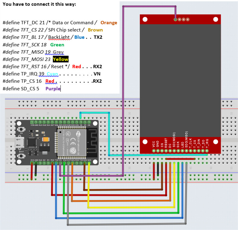
You have to connect it this way:
#define TFT_DC 21 /* Data or Command /
#define TFT_CS 22 /
SPI Chip select /
#define TFT_BL 17 /
BackLight /
#define TFT_SCK 18
#define TFT_MISO 19
#define TFT_MOSI 23
#define TFT_RST 16 /
Reset */
#define TP_IRQ 39
#define TP_CS 16
#define SD_CS 5

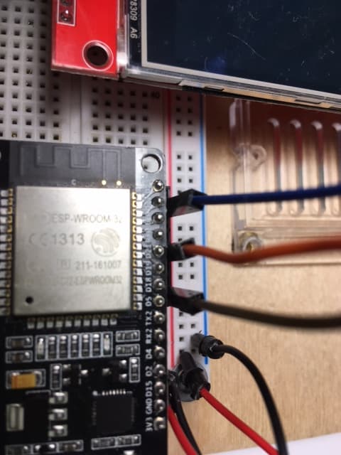
You should take pictures from vertical above the device. Only if you take the picture from vertical above it will be easy to see which pin is connected to what

In lack of such a picture from you I use this picture to explain the wiring

best regards Stefan

at first I write some words in

big letters

the meaning is not shouting
the meaning is just: really really do it this way. Take it serious

I tried to conclude which IO-pin is connected to what and tried to add the IO-pin numbers but finally I gave up because it

can't

be identified clearly


You should really take

new

pictures
from

vertically above

and make sure
the pictures are

sharp

and

easy to read

best regards Stefan

I did some new googling trying to find a tutorial that shows all details

I haven't verified this tutorial with a practical test
but from the detailed descriptionof I guess that there is a good chance that it will work

still the description of this tutorial explains why it is (sometimes) so hard to get a graphical display to work.
almost everybody is using a different combination of microcontroller, library and IO-pin definition.
Even in this tutorial the pin-definitions have to be modified from the default configuration in the example files.

best regards Stefan

Stefan: Thank you for your very well written and detailed description of what to do and how to do it. I'm sure that you will have a good New Years celebration. I know what I will be doing. I do have one or two questions related to your MSP2807 display pin out definitions.
On the backside of my display PCB I have pins labeled:

 T_IRQ   .  .  .  you have TP_IRQ 
 T_DO
 T_DIN
 T_CS .  .  .  .  .  .  .  you have TP_CS
 T_CLK
 SDO(MISO) .  .  .  you have MISO
 LED .  .  .  .  .  .  .   you have BL
 SCK
 SDI(MOSI) .  .  .    you have MOSI
 DC
 RESET .  .  .   .  .    you have TP_RST
 CS
 GND
 VCC
 
 SD_CS
 SD_MOSI
 SD_MISO
 SD_SCK

Does the sketch deal with these differences in the display pin labels?
There is only one connection to the four SD pins, SD_CS.  Is that correct?

I will take pictures from the vertical, and post only those in good focus.

Best wishes and Happy New Year

Post the code you used to perform these tests.

a7

IO-pins related to the SD-card-socket hence the "SD"

I'm not too familiar with the SPI-interface naming.
It depends of the perspective
SDO is an abreviation for Serial Data Out
Now what is data-"out" for the microcontroller is data-"in" for the display

at Wikipedia there is a picture

That shows the standard-names MOSI / MISO
These names MOSI / MISO clearly say what is what.
Master is the microcontroller
wikiepedia also epxlains the names SDO/SDI

You should really post a sharp and easy to read picture of your PCB with the IO-pin-labels.

Each display-pin has a function.
Clock-signal
Data-input
Data-output
Chip-Select
And additionally this display has a pin "DC" Data or Command

From the names "Data" / "Command" I conclude that the driver-chip has another functionality that distinguishes between "data" and "commands" (whatever this means in detail)

You have to compare the abreviations on the display and conclude what each abreviation's function is.

There are differencies like "SCK", "SCL", "SCLK" which all mean the function serial clock

What I do not know (yet) is of you accidently change MISO/MOSI if it just does not work or I a too high current can damage the display-driver-chip or the microcontroller-chip

best regards Stefan
This is another reason why I would search for the most detailed documented project description using a 2,8" SPI TFT 240x320 pixel-display with ILI9341-driver-chip.
Where the documentation should include

  • mentioning all important details about the display as there are physical size, pixel-resolution, interfacetype

  • mentioning all important details of the microcontroller

  • a wiring-diagram that shows IO-pin names of the display and the ESP32

  • a ready to flash demo-code

best regards Stefan

Stefan: Thank you for the very detailed description. Based upon my understanding of your previous set of comments, I created a wiring diagram following your comments. I used the bread board window of my Fritzing application to draw the diagram. See below:

I think that you can enlarge this image to check the pin out connections. The pin labels on the MSP2807 are those printed on the back side of the display PCB.