I’m building a circuit with an Arduino Uno, an L293D motor driver, two DC motors, a potentiometer, and two buttons. The battery powers the motors while the Arduino handles logic. The potentiometer adjusts speed, and the buttons let me start or stop both motors safely without overloading them.
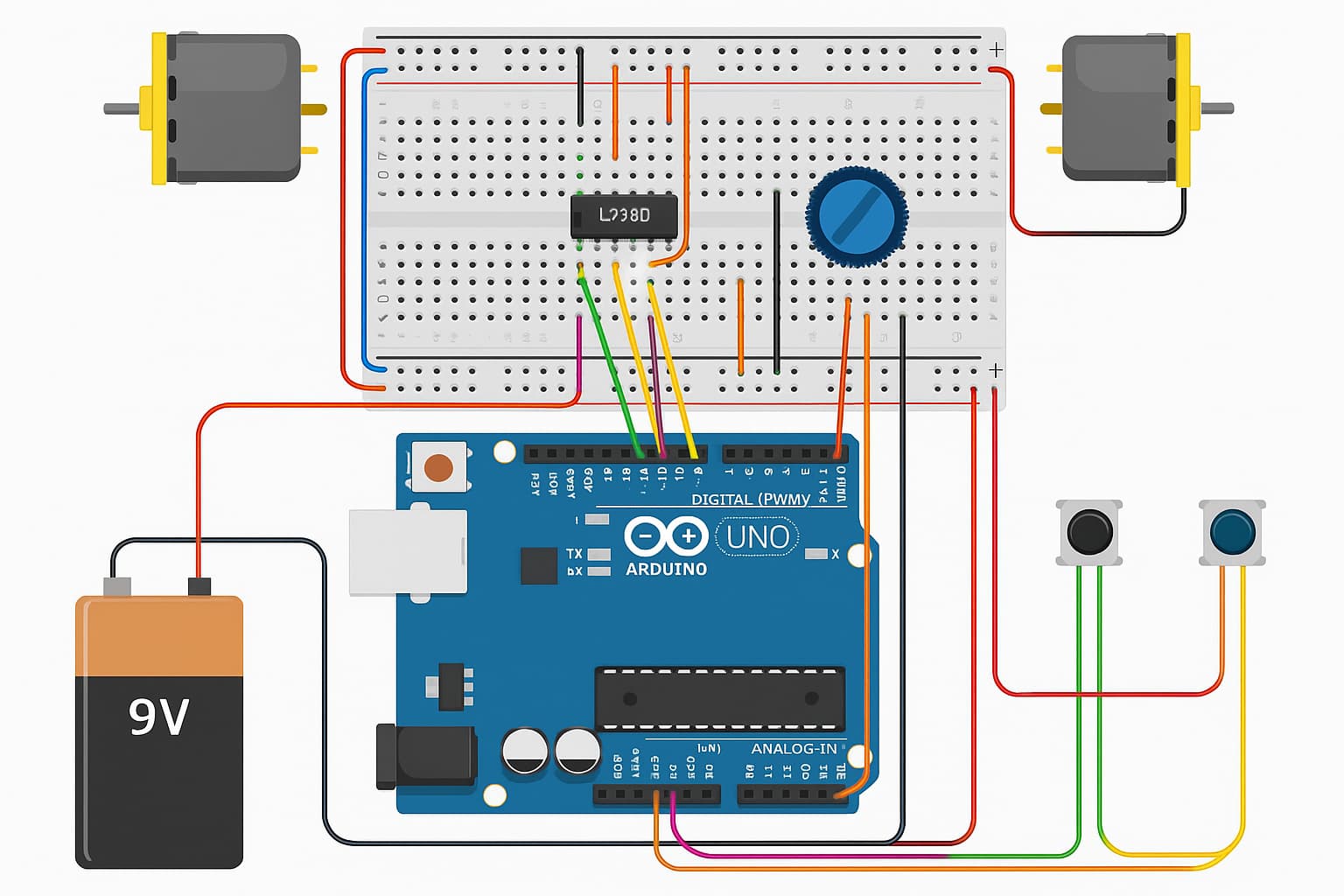
This is my circuit and it is not working.
(upload://qtCFHkZljicIsFQaPfDJhMPgElh.jpeg)
If this doesn't work can someone help me create a new circuit and code?
Your physical layout diagram (it is not a schematic) shows only one wire to one motor and no wires to the other motor. How on earth do you think that will work?
It also shows the buttons wired up wrong, they should be wired across the diagonal, either diagonal will work.
That picture you posted is a Chat GPT created image. All bets are off as Chat GPT just makes things up when it doesn't know something. It has made up a mess.
Can you please post a copy of your circuit, a picture of a hand drawn circuit in jpg, png?
Hand drawn and photographed is perfectly acceptable.
Please include ALL hardware, power supplies, component names and pin labels.
You should be building your project one piece at a time and ensure that works the way you want! Start with one device, one button switch and get that to work. It required only two wires!
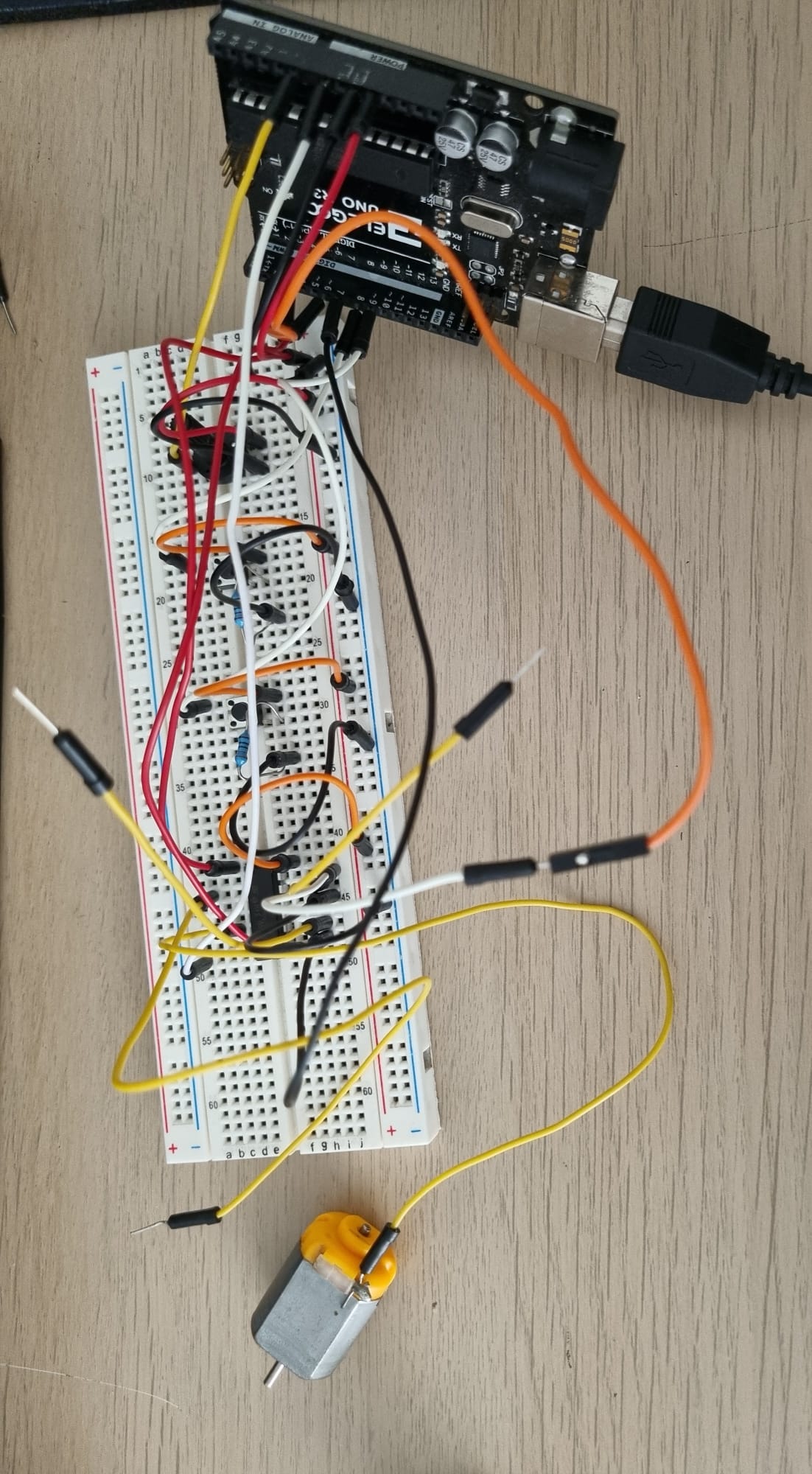
I uploaded my circuit. Power supply is the standard Arduino R3 USB port. Contains 1 potentiometer, 2 buttons with resistors, breadboard, jumperwires, L293D motor. Here's the new code:
const int potPin = A0;

const int motorAEnable = 3;

const int motorAIn1 = 4;

const int motorAIn2 = 5;

const int motorBEnable = 6; const int motorBIn1 = 7; const int motorBIn2 = 2;

const int buttonOn = 8; const int buttonOff = 9;

bool motorsOn = false;

void setup() { pinMode(motorAEnable, OUTPUT); pinMode(motorAIn1, OUTPUT); pinMode(motorAIn2, OUTPUT);

pinMode(motorBEnable, OUTPUT); pinMode(motorBIn1, OUTPUT); pinMode(motorBIn2, OUTPUT);

pinMode(buttonOn, INPUT); pinMode(buttonOff, INPUT);

Serial.begin(9600); }

void loop() { int potValue = analogRead(potPin); int speed = map(potValue, 0, 1023, 0, 255);

if (digitalRead(buttonOn) == HIGH) { motorsOn = true; }

if (digitalRead(buttonOff) == HIGH) { motorsOn = false; }

if (motorsOn) {digitalWrite(motorAIn1, HIGH); digitalWrite(motorAIn2, LOW); analogWrite(motorAEnable, speed);

digitalWrite(motorBIn1, HIGH);

digitalWrite(motorBIn2, LOW);

analogWrite(motorBEnable, speed);

} else { analogWrite(motorAEnable, 0); analogWrite(motorBEnable, 0); }

delay(50); }```
it is highly recommended to not run motors from the arduino 5V.
L29x has significant voltage drop. astarting with 5V almost nothing will be left for the motor. It should be sufficient to turn the unloaded motor though.
Why is there only one wire on your motor?
Buy jumper wires... make them different lengths. That way they can lay flat on the breadboard.
Do not use two pins next to eachother on the buttons...
Make a schematic diagram of your circuit...
Use the upper red lina as positive rail and the bottom blue line as negative rail...
And please modify your code with proper indentation.
I can use a power supply module with batteries for the breadboard. One question, is the ground supposed to be one section, not the whole line? As in the photo, lines are split into sections. Are pins on buttons supposed to be diagonal?
my guess is that your blue and red line are continuous. on some breadboards they are not.. (check with dmm or led plus resistor).
diagonal is not needed, but by far the easiest way to guarantee that it is properly connected. Otherwise you depend on how the button is put into the board... and from your picture we cannot check that.
the L29x has 2 plus connectors. one should be fed with your batteries. 6AA (9V) would be good.
Can you help with building a new circuit please? I tried what you said and it still doesn't work. Checked indentation as well. I dont know if this is allowed but I'm willing to pay for a working circuit diagram
I posted the code with the real indentation. I used the link to the robot site and it worked, but without any buttons or potentiometers. I tried incorporating potentiometers and buttons but to no avail