I am trying to get some temperature sensors connected to my solar input and outflow for my pool. I have an konnected board which I believe is just an Arduino. I have it all ready to drive a WebCore piston that will interface with Alexa so she can tell me when to manually flip my solar valve to regulate the temperature (usually just need to shut it down every few days in the Florida summer to keep the pool from getting too warm)
I have been able to get the sensors to work (via smartthings) when they are either close to the board (short cable or just a breadboard) and connected to an 80' run of cat5 cable prior to feeding it through my attic. It was a simple run, I do not believe I have any connectivity issues in the wiring.
I have read everything I can about using a 4.7k resistor, using 2.2k, or 150ohm in various configurations. I have put the 4.7k at the near end and the far end. I have used 2.2k at both ends (one at a time). I sometimes get a single one of two sensors to read. Currently there is 4.97v across the power and ground at the far end and with the 4.7k crossing the power and data lines, I get 3.04v at the far end. Using the 2.2k I get about 3.75 or 4.0v on the data line.
I'm not a hardware guy, just a software guy shooting in the dark
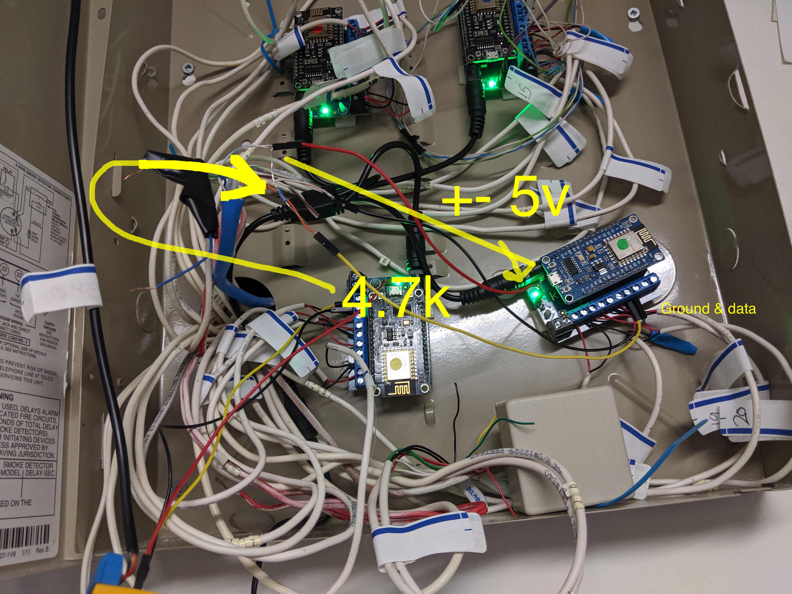
Attached are some pictures of my setup. One picture shows the Konnected board and the other shows the far end by my pool pump where I have a simple breadboard and two DS18b20's plugged in.
I have been messing with this for weeks after getting it to all work in an afternoon before running the wire (it is the same wire, just now it is in the attic vs in a coil on the ground) Any insight, help greatly appreciated.
That doesn’t look like cat 5 cable to me, more like multicore alarm cable .
At such long distances the cable type is important.
You may also have ground loops or other problems (!!) with your wiring , sorry but it’s a mess with a lot of dodgy connections .
If you google there are some guides on using long cable lengths with these sensors.
Make a simple ( tidy) circuit with just the temp sensors on and get that working first with some of the Arduino library examples, run at low resolution if you can ( see examples )
The longest run I have ever used with a DS18B20 is one meter.
According to the DS datasheet, the pull-up resistor must be able to restore the bus back to a high within 14us. High on an Uno is anything over 2.5V. This means that the capacitance of the wire can't be over 400pF.
According to Belkin, Cat 5e UTP cable has a nominal 300pF per 100 meters. Add to this the internal capacitances of the DS18B20 devices and the Arduino I/O port and 100 meters would be an absolute maximum. A smaller pullup resistor would help offset the cable capacitance, but not so small that the DS devices would not see a data high.
SteveMann:
The longest run I have ever used with a DS18B20 is one meter.
According to the DS datasheet, the pull-up resistor must be able to restore the bus back to a high within 14us. High on an Uno is anything over 2.5V. This means that the capacitance of the wire can't be over 400pF.
According to Belkin, Cat 5e UTP cable has a nominal 300pF per 100 meters. Add to this the internal capacitances of the DS18B20 devices and the Arduino I/O port and 100 meters would be an absolute maximum. A smaller pullup resistor would help offset the cable capacitance, but not so small that the DS devices would not see a data high.
Thanks for the response. I've read and re-read that doc 100x over the past few weeks So my 80' is only about 25 meters. Thought I did what it suggested. I use one twisted pair for data & ground, then one other wire for power. I have grounded the rest of the wires (and tried without grounding them.) ...
I will try some other resistor values. I have the 4.7k on there right now and it is reading one of two DS18b20's on the breadboard, the other doesn't seem to respond ...
Multiple processors (four?) is usually a beginner's mistake.
Never heard of port expanders?
Leo..
Thanks Leo. Those aren't my boards. I bought a kit called 'konnected' it is a boxed solution that is designed to replace your wired alarm panel with a smart panel. It interfaces with Smartthings or other various smart hubs. Works very well. I believe it is just an arduino. I have 4 of them because I have so many zones/doors/windows etc in the house. Their software stack also supports temp sensors etc and reports them into the smartthings hub.
Thanks for all the responses. Yeah, the box is a bit messy. Most of this is just the existing wired alarm panel and those white wires are indeed alarm wires coming from the 25 or 30 sensors around the house. I'm using the konnected (https://konnected.io/) product with 4 panels to give me 24 zones. I believe these are arduino based but they use the connected software stack.
I know there quite a bit of work has been done in various open source libraries for the 1-wire protocol to enable it to work without resistors, I believe they mostly just play with some of the wait times for the signal to settle/clear. In any case, the konnected stack appears to just adopt most of the open source libraries. I should check if they have the changes to support w/o the resistor (from my tests w/o ... I would say no
I should have taken a better picture, my bad. This is all running over cat5, you can see the blue sheath in there if you look close. There are 4 twisted pairs one is used for data+ground, another single wire is for power, the other in the pair is grounded.
As I said in my initial post, I was able to get this all working as shown prior to running the cat5 up through the attic and down the side of the house out by the pool pump. In that setup I had three sensors all reporting regularly over this same cat5 wire.
I have a second sensor on a separate alarm panel that is just taking the ambient temp by the panel, this is just a simple direct connect via a breadboard power, ground, data and it works fine.
fcassirer:
I have read everything I can about using a 4.7k resistor, using 2.2k, or 150ohm in various configurations. I have put the 4.7k at the near end and the far end. I have used 2.2k at both ends (one at a time). I sometimes get a single one of two sensors to read. Currently there is 4.97v across the power and ground at the far end and with the 4.7k crossing the power and data lines, I get 3.04v at the far end. Using the 2.2k I get about 3.75 or 4.0v on the data line.
The DS18b20 spec says the sensor minimum voltage is 3.0V, so I would expect the 3.04V you measured would provide intermittent measurements. Use the 2k2 resistor at the sensor end.
You did say that the setup worked through 80 ft of CAT5 cable on the bench, but only got flaky when you ran the CAT5 through the attic space?
If that is what you said, then I am suspecting that you are picking up some interference (need a scope) or adding to the cable capacitance that screws with the timing (need a scope), like you ran it on a metal surface or in a metal condit or bundled with Romex lighting wire.
Do you have more CAT5 cable that you could repeat the bench test with 80 ft of cable like you did before? If that works, then can you try a different path through the attic?
Don't use any pairs for single-ended communication. Can you use one pair as ground, one pair as power and another pair for data?
Look up "transmission line" theory. Without appropriate termination impedances, your data will be bouncing off both ends of the cable and mixing up the middle. 3.3V is very sensitive to this.
Or just move to a higher voltage for the wire. That will work to shout "louder" than the interference. (Reflections are also louder but that may not be the worst problem you have.) I think i2c voltage conversion boards will work for this.
SteveMann:
The longest run I have ever used with a DS18B20 is one meter.
I've used a lot longer than that!
According to the DS datasheet, the pull-up resistor must be able to restore the bus back to a high within 14us. High on an Uno is anything over 2.5V. This means that the capacitance of the wire can't be over 400pF.
Wrong calculation there, RC for 400pF and 4k7 is 1.9µs
According to Belkin, Cat 5e UTP cable has a nominal 300pF per 100 meters.
Since typical cables are always in the 20 to 100pF/m range, this is clearly way out.
I looked up the spec of CAT5 and its nominal 52pF/m, so 100m is 5.2nF, not 300pF.
With 4k7 pullup and 14µs time-constant thats a limit for capacitance of 3nF, or about 60m of CAT5.
MorganS:
Don't use any pairs for single-ended communication. Can you use one pair as ground, one pair as power and another pair for data?
Look up "transmission line" theory. Without appropriate termination impedances, your data will be bouncing off both ends of the cable and mixing up the middle. 3.3V is very sensitive to this.
Or just move to a higher voltage for the wire. That will work to shout "louder" than the interference. (Reflections are also louder but that may not be the worst problem you have.) I think i2c voltage conversion boards will work for this.
What this means is use one pair as ground+signal, and another pair as +5V+ground. Common the grounds at each device and at each end, and use 100nF decoupling capacitor from +5V to ground at each device for maximum reliability.
MorganS:
Don't use any pairs for single-ended communication. Can you use one pair as ground, one pair as power and another pair for data?
I agree. Use this:
Grn/Grn-wht = GROUND
Org/Org-wht = +5V
Blu/Blu-wht = DATA (GPIO)
Brn/Brn-wht = NO CONNECTION
When you use a pair for data and ground, (Blu = data, Blu-wht = GROUND), you are adding capacitance to the data line, lengthening the low to high response on the net.