HELP! I2C LCD no display no backlight

I've tried to do my first project for the LCD but when I was using this code it only gives me the power light on without any other feedback.

I'm using mega 2560, and the addedss of my stuff is 0x3F.

#include <Wire.h> 
#include <LiquidCrystal_I2C.h>

// Set the LCD address to 0x27 for a 16 chars and 2 line display
LiquidCrystal_I2C lcd(0x27, 16, 2);

void setup()
{
  // Robojax code for LCD with I2C
  // initialize the LCD, 
  Wire.begin(3-2-1-0-4-5-6-7);
  lcd.begin();
 
  // Turn on the blacklight and print a message.
  lcd.backlight();
  // Robojax code for LCD with I2C


}

void loop()
{
  
  //start of loop Robojax code for LCD with I2C
  lcd.clear();
  lcd.print("Robojax");
  lcd.setCursor (0,1); // go to start of 2nd line
  lcd.print("Hello World!");
  //lcd.print(millis() / 1000);
  delay(500);
 //end of loopcode Robojax code for LCD with I2C
}


20200323171756.png

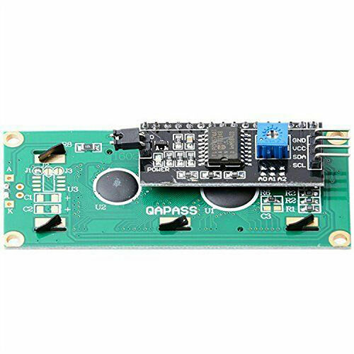
No problem. Most likely You need to connect two pins on the display board, or the IC2 board. Mostly a little black strap, 0.1" wide is used for that. Sometimes Ebay & Co forget to supply that. Look for two square profile pins on the display kit haing the text "LED" printed next to them.

Railroader:
No problem. Most likely You need to connect two pins on the display board, or the IC2 board. Mostly a little black strap, 0.1" wide is used for that. Sometimes Ebay & Co forget to supply that. Look for two square profile pins on the display kit haing the text "LED" printed next to them.

Thanks for reply, I didn't buy them, they came from my cousin so I'm really not sure if I can find the strap. Is there anything I can use to replace? Like an electro tape maybe?

The bus scan shows you the display is at 0x3F but you are declaring your lcd at address 0x27.

Also, what is this?

  Wire.begin(3-2-1-0-4-5-6-7);

.
That can't possibly be correct.

Use a tiny, none isolated copper wire for testing and wire a number of turns. A paper clip might do, for testing.

@blh64 As I remember the back light ought to be lit up as soon as Vcc is present, but I might be wrong.

blh64:
The bus scan shows you the display is at 0x3F but you are declaring your lcd at address 0x27.

Also, what is this?

  Wire.begin(3-2-1-0-4-5-6-7);

.
That can't possibly be correct.

I've already tried 0x3F, it doesn't change anything. And for my understanding is 0x3F is totally same with 0x27? I found some people saying online that 0x3f is working as same as 0x27(How to use an I2C LCD 16x2 with Arduino - Ardumotive Arduino Greek Playground). For the wire.begin() thing, I just face the problem before I add them in and someone in the forum says that add wrie.begin() may help. the address comes from the library that I'm using.

#include <Wire.h> 
#include <LiquidCrystal_I2C.h>

// Set the LCD address to 0x27 for a 16 chars and 2 line display
LiquidCrystal_I2C lcd(0x3F, 16, 2);

void setup()
{
  // Robojax code for LCD with I2C
  // initialize the LCD, 
  //Wire.begin(3-2-1-0-4-5-6-7);
  lcd.begin();
 
  // Turn on the blacklight and print a message.
  lcd.backlight();
  // Robojax code for LCD with I2C


}

void loop()
{
  
  //start of loop Robojax code for LCD with I2C
  lcd.clear();
  lcd.print("Robojax");
  lcd.setCursor (0,1); // go to start of 2nd line
  lcd.print("Hello World!");
  //lcd.print(millis() / 1000);
  delay(500);
 //end of loopcode Robojax code for LCD with I2C
}

.
I just tried this one, doesn't work T_T

Change to a better library. Use hd44780. It finds the I2C address by iyself.
Here0 is a piece of code showing a l
7
ittle from my projs.

//Ver 191221c Styr med potentiometer
//Ver 191221d Universal buton_read installed

//I2C for LCD
#include <Wire.h>
#include <hd44780.h>
#include <hd44780ioClass/hd44780_I2Cexp.h>

hd44780_I2Cexp mylcd; // declare lcd object: auto locate & config exapander chip

// LCD geometry
#define LCD_COLS 16
#define LCD_ROWS 2

#define PWM1_pin 5
#define PWM2_pin 3
//#define dir_pin 4
#define dir_select_pin 2
#define speed_pin A2
#define auto_return_pin 5
#define auto_return_end_pin 6

boolean direction_bwd, last_dir = true;
int PWM_out, dsp_toggle;
unsigned long last_button_read, dsp_time;
  bool tst_dir;

void setup()
{
  Serial.begin(115200);
  bool  status = mylcd.begin(LCD_COLS, LCD_ROWS);
  if (status) // non zero status means it was unsuccesful
  {
    status = -status; // convert negative status value to positive number

    // begin() failed so blink error code using the onboard LED if possible
    hd44780::fatalError(status); // does not return
  }
  mylcd.clear();

Mind the remarks by the other helpers!

Railroader:
Use a tiny, none isolated copper wire for testing and wire a number of turns. A paper clip might do, for testing.

@blh64 As I remember the back light ought to be lit up as soon as Vcc is present, but I might be wrong.

So you mean it might because of the bad contact? OK I see, I'll try to make them. Thank you

Is is called "strap", a little plug used to select options and so on. BUT, be careful! Don't short just any pins! Look for the text printed on the circuit board, LED!

No, not bad contact. Totally missing connection.

If the scan shows 0x3f then that is what you must use.

Once you get the backlight up and running, you may have to adjust the contrast via the blue square pot with the program running.

Jumper is shown in image below. Black square jumper just above the black circle.

@bluejets
Thanks! Just what I tried to tell.

Railroader:
Change to a better library. Use hd44780. It finds the I2C address by iyself.
Here0 is a piece of code showing a l
7
ittle from my projs.

//Ver 191221c Styr med potentiometer

//Ver 191221d Universal buton_read installed

//I2C for LCD
#include <Wire.h>
#include <hd44780.h>
#include <hd44780ioClass/hd44780_I2Cexp.h>

hd44780_I2Cexp mylcd; // declare lcd object: auto locate & config exapander chip

// LCD geometry
#define LCD_COLS 16
#define LCD_ROWS 2

#define PWM1_pin 5
#define PWM2_pin 3
//#define dir_pin 4
#define dir_select_pin 2
#define speed_pin A2
#define auto_return_pin 5
#define auto_return_end_pin 6

boolean direction_bwd, last_dir = true;
int PWM_out, dsp_toggle;
unsigned long last_button_read, dsp_time;
  bool tst_dir;

void setup()
{
  Serial.begin(115200);
  bool  status = mylcd.begin(LCD_COLS, LCD_ROWS);
  if (status) // non zero status means it was unsuccesful
  {
    status = -status; // convert negative status value to positive number

// begin() failed so blink error code using the onboard LED if possible
    hd44780::fatalError(status); // does not return
  }
  mylcd.clear();


Mind the remarks by the other helpers!

I've toke a few hours to figure out this lab but still couldn't understand the function lmao. Is it just need me to connect the LCD directly without I2C or I should link the SCL&SDA for this code?

// vi:ts=4
// ----------------------------------------------------------------------------
// HelloWorld - simple demonstration of lcd
// Created by Bill Perry 2016-07-02
// bperrybap@opensource.billsworld.billandterrie.com
//
// This example code is unlicensed and is released into the public domain
// ----------------------------------------------------------------------------
//
// This sketch is for LCD modules that have a native I2C interface such as
// PCF2119x, PCF2116, or certain RayStar LCDs rather than those LCD modules that
// use an i/o expander chip based based backpack.
// NOTE:
//	These devices usually need external pullups as they typically are not on
//	the module.
// WARNING:
//	Use caution when using 3v only processors like arm and ESP8266 processors
//	when interfacing with 5v modules as not doing proper level shifting or
//	incorrectly hooking things up can damage the processor.
// 
// Sketch prints "Hello, World!" on the lcd
//
// If initialization of the LCD fails and the arduino supports a built in LED,
// the sketch will simply blink the built in LED.
//
// ----------------------------------------------------------------------------
// LiquidCrystal compability:
// Since hd44780 is LiquidCrystal API compatible, most existing LiquidCrystal
// sketches should work with hd44780 hd44780_I2Clcd i/o class once the
// includes are changed to use hd44780 and the lcd object constructor is
// changed to use the hd44780_I2Clcd i/o class.

#include <Wire.h>
#include <hd44780.h>
#include <hd44780ioClass/hd44780_I2Clcd.h> // i2c LCD i/o class header

// Note, i2c address can be specified or automatically located
// If you wish to use a specific address comment out this constructor
// and use the constructor below that specifies the address

// declare the lcd object for auto i2c address location
hd44780_I2Clcd lcd;

//
// enter address of LCD.
// Addresses seen so far include:
// - 0x3a, 0x3b (PCF2119x)
// - 0x3c (unknwon chip)
// - 0x3d (unknwon chip)
// - 0x3e (unknwon chip)
// - 0x3f (unknwon chip)

// declare i2c address and constructor for specified i2c address
//const int i2c_addr = 0x3e;
//hd44780_I2Clcd lcd(i2c_addr); // use device at this address


// LCD geometry
const int LCD_COLS = 16;
const int LCD_ROWS = 2;
void setup()
{
int status;

	// initialize LCD with number of columns and rows: 
	// hd44780 returns a status from begin() that can be used
	// to determine if initalization failed.
	// the actual status codes are defined in <hd44780.h>
	// See the values RV_XXXX
	//
	// looking at the return status from begin() is optional
	// it is being done here to provide feedback should there be an issue
	//
	status = lcd.begin(LCD_COLS, LCD_ROWS);
	if(status) // non zero status means it was unsuccesful
	{
		status = -status; // convert negative status value to positive number

		// begin() failed so blink error code using the onboard LED if possible
		hd44780::fatalError(status); // does not return
	}

	// Print a message to the LCD
	lcd.print("Hello, World!");
}

void loop() {}

bluejets:
If the scan shows 0x3f then that is what you must use.

Once you get the backlight up and running, you may have to adjust the contrast via the blue square pot with the program running.

Jumper is shown in image below. Black square jumper just above the black circle.

I see, thanks for reminding me.

So in that case, am I suppose to wrap both of the pins with copper wire? I've tried to use my multimeter to check the voltage of those pins, it just gives me a little reading which likes 0.12v, is this normal? I've also use my cable to connect them together, the backlight light up immediately. But I still can't get the display what I write on the code

#include <Wire.h> 
#include <LiquidCrystal_I2C.h>

// Set the LCD address to 0x27 for a 16 chars and 2 line display
LiquidCrystal_I2C lcd(0x3F, 16, 2);

void setup()
{
	// initialize the LCD
	lcd.begin();

	// Turn on the blacklight and print a message.
	lcd.backlight();
	lcd.print("Hello, world!");
}

void loop()
{
	// Do nothing here...
}

I appreciate your help, thx a lot.

ps:Oh, should these two pins be connected in series? No wonder I can't detect the voltage lmao

Did you adjust your contrast? That’s the blue thing

shenlongyzc:
I've toke a few hours to figure out this lab but still couldn't understand the function lmao. Is it just need me to connect the LCD directly without I2C or I should link the SCL&SDA for this code?

Not quite sure what you mean by this.

Referring to the LCD with the I2c backpack, you need to connect 5V (Arduino) to the VCC (LCD), Ground to Ground, SDA to SDA and SCL to SCL.
Your photo showed correct clock and data line connections originally although difficult to see the power connections.

You don't have it connected to 3.3V by any chance...?

wolframore:
Did you adjust your contrast? That’s the blue thing

Yeah, but that just for adjust the contrast. there are no words showing up, just some... Idk, like digital squareds

shenlongyzc:
Yeah, but that just for adjust the contrast. there are no words showing up, just some... Idk, like digital squareds

Shorthand comments not recognised, please send English text ( Idk....no understand)
Send photo of what you have.

You have not answered the question about voltage.

Other than that , have you simply tried the I2c example for an I2c LCD in the examples in the IDE..??

bluejets:
Not quite sure what you mean by this.

Referring to the LCD with the I2c backpack, you need to connect 5V (Arduino) to the VCC (LCD), Ground to Ground, SDA to SDA and SCL to SCL.
Your photo showed correct clock and data line connections originally although difficult to see the power connections.

You don't have it connected to 3.3V by any chance...?

I was mean the two pins at the left side in your picture, the two pins hiding in the black square, sorry I'm not a native English speaker, my grammar is terrible.

No, I didn't, GND stay in GND, VCC goes to 5V, definitely lol

Could you tell me how do I send a picture on the reply?

Click on reply at the bottom. Then on add attachments.It allows you to add photos etc. from your pc.