I an making a project using arduino(which is compulsory ).
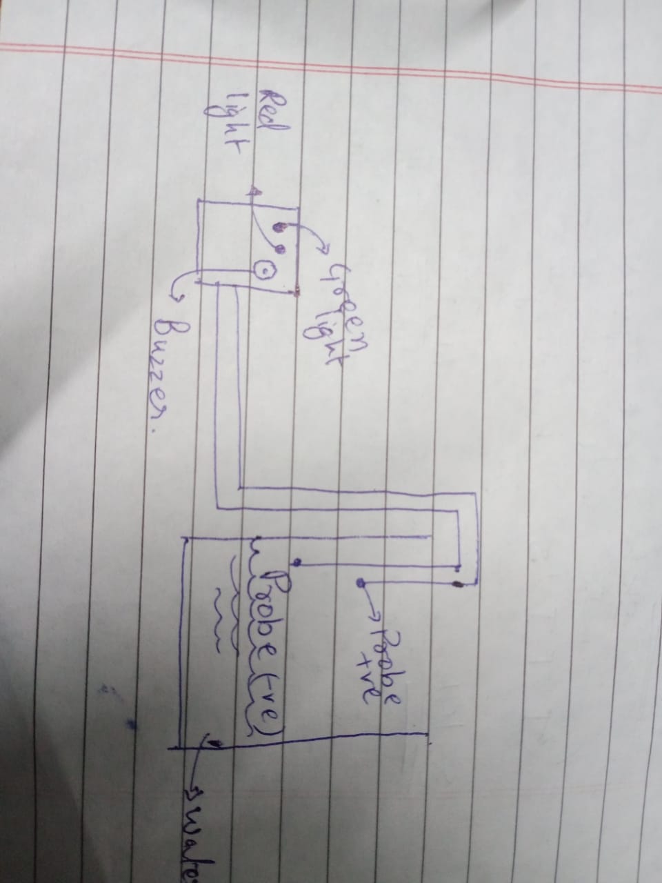
the project the "Water tank overflow turn off switch ". The project aims to turn of the switch using servo motor (the switch i the same as the fan round switch ).
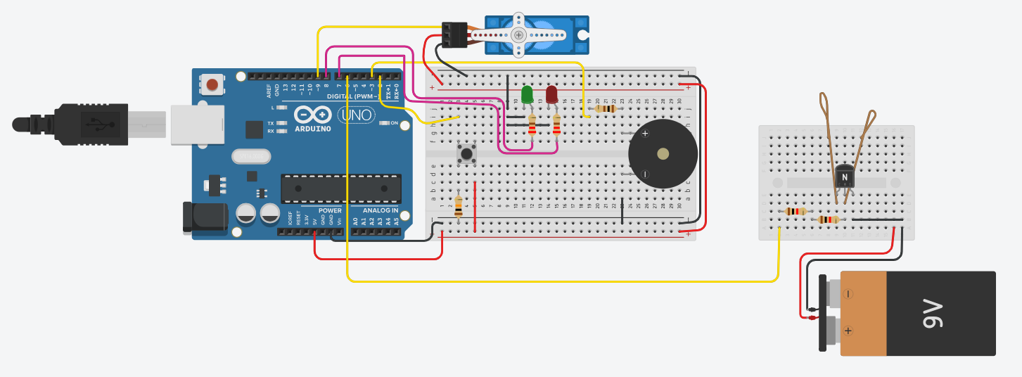
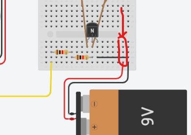
i need help in connecting the BC547 transistor and cant seem to get the circuit right like where the ends of probe go or how the collector and emitter should be attached to the battery.
Since i am using Tinkercad to make the circuit the NP_N transistor is to be replaced by BC547.
(i have attached 2 1K ohm resistors to the transistor )
The only problem i am facing in the connection of transistor and how will the arduino read its signal .
First of all, do you know what ground (GND) is? It's very fundamental in electronics, so you should know. Then you just add to yep circuits ground together, and voilà, you got common ground!
But do you really need the 9 V circuit? Why don't you use the 5 V from the Arduino instead? Distance?
The Arduino as well? If so you'll be changing batteries often.
I think it's time to get us up to date with your project. You have a water tank that's not supposed to or must not overflow. How far away is the Arduino located from the sensor? What is to be done when the alarm goes off?
Don't you have any power source next to Arduino?
And what kind of water is to be monitored? Because if it's for humans (e.g. drinking water or coffee) it isn't a good idea to put copper wires inside.
Anyway, why don't you take a look at this project I made several years ago? Maybe it could give you some useful hints:
to answer your question
The water tank must not overflow.
bc547 will is at 40 cm wire at least and arduino at 60 to 80 cm.
i am using a modified switch so the the servo motor can rotate it
As to where it will be used :
Fish tank
Water tank where plants are grown (as they require frequent water change)
These are the only problems i am currently addressing in the project .
Good. So my advise is to avoid any contact with copper wires, using a non-invasive solution, like ultrasonic sensor (it was the solution I implemented and worked for almost 10 years, the lifetime of that espresso machine). It can also give you a good precision level measure (if the water is steady), not only just the limit reached, so you can define the limits just on the software side...