I just edited the code to be as wanted
Welcome to the forum. I'm sure some of us had less fun on the first posting we ever made here, so just roll with the advices and it will all be history and like most history totally forgotten.
If that's the code, which looks plausible, this
else {
    digitalWrite(redLedPin, LOW);   // Turn off red LED
    digitalWrite(blueLedPin, LOW);  // Turn off blue LED
    lcd.setCursor(0, 1);
    lcd.print("System: Stable ");
is a logic mistake.
The response of the system when it is stable (between the set points of too hot and too cold) should be to leave things as they are.
I'm not sure the rest of the logic supports, or more accurately if that is a very good idea at all:
- turn on the heat when it is too cold don't turn it off until it is warm enough
- turn on the cooling when it is too hot, don't turn it off until it is cold enough
The implicaction is that in the comfort zone you will always be either heating or cooling… which is why real thermostats have an AC mode for seasons when it is usually too hot and a HEAT mode for, well you get the point.
With your logic, the system would, for example, turn on the heat when it was a wee bit cold, and immindiantly the temperature goes above the lower threshold it would turn off. On and off and on and off.
Which is usually the roll of the two temperatures, to provide hysteresis, a band in the middle where we might be heating to reach the upper threshold, temp going up, or not heating whilst the temp gradually falls.
I don't know how I would do AC and HEAT at the same time.
a7
Your schematic is too blurry to read.
If the diagram you show in your edited post #1 is the actual diagram, then you still have the LEDs shorted to 5V.
Yes I add the limits which are 20-30
If the temp is under 20 the red will turn on (I add led which is symbol for heater since there is no heater in tinkercad) ,if the temp is above 30 the blue led should turn on(blue led is symbol for cooler since there is no cooler in tinkercad)
Also if the temp is btw 20 to 30 both leds should turn of
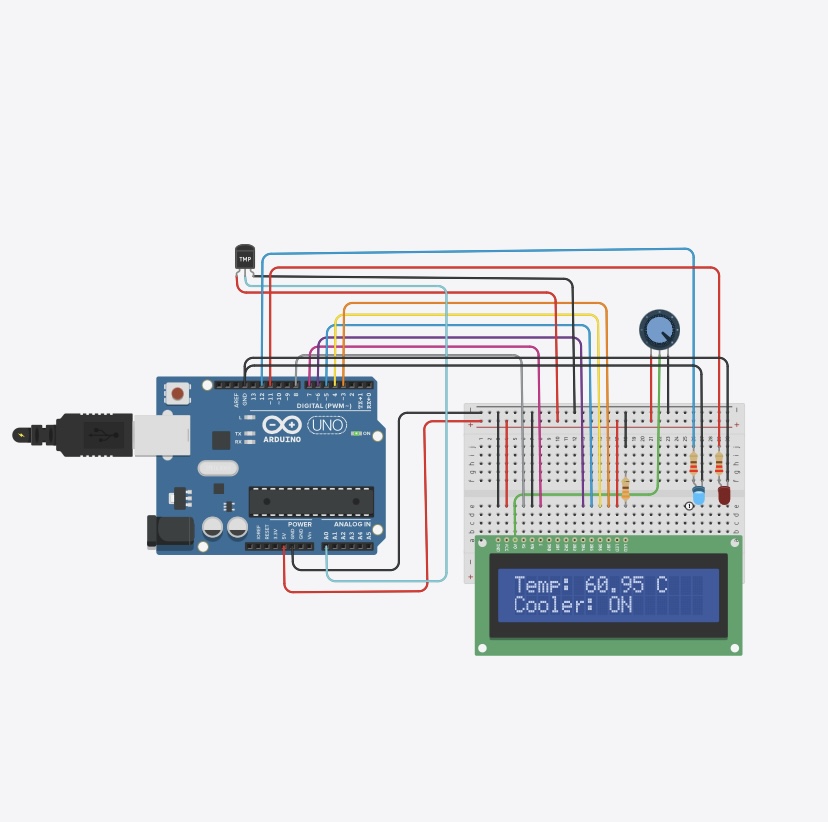
Also the temp will be displayed on the lcd
In my circuit the lcd is working but I have a problem where both leds are on eventhough I change the temp
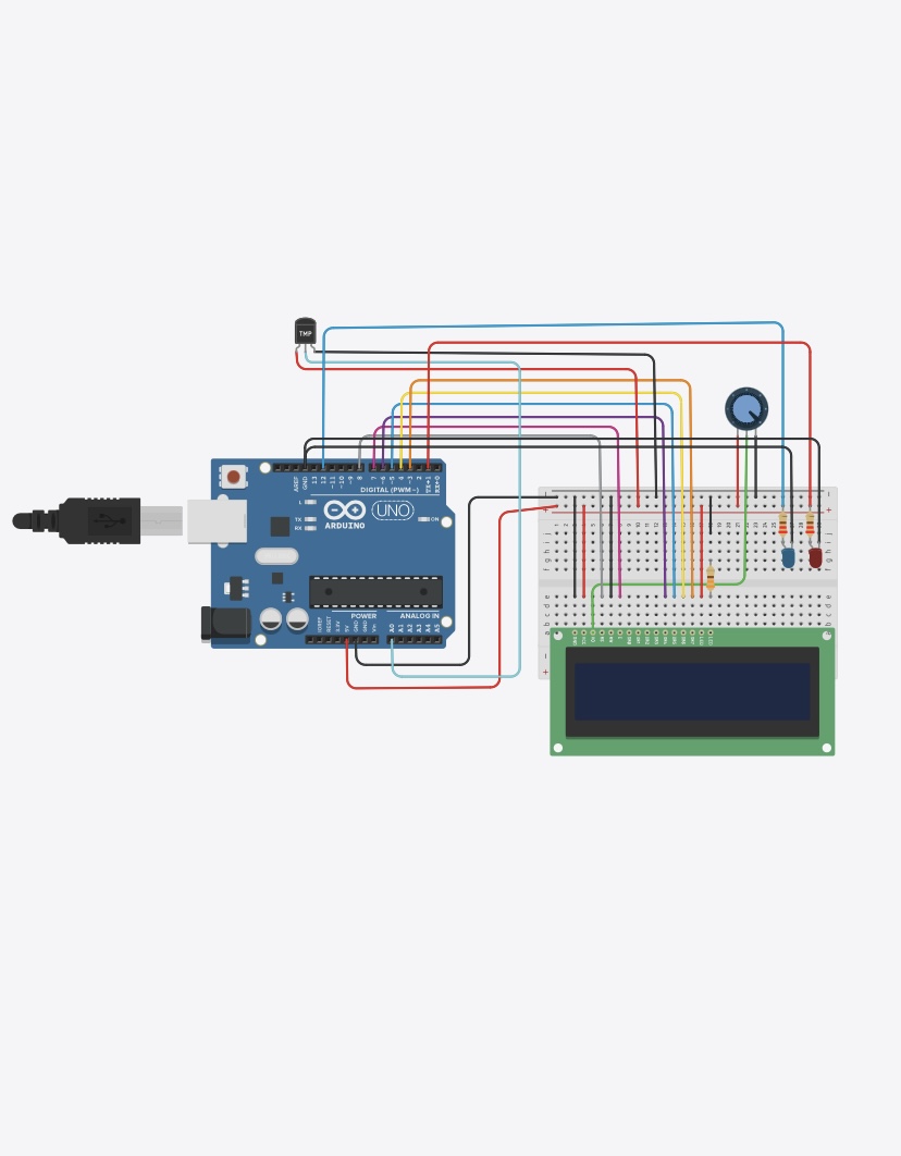
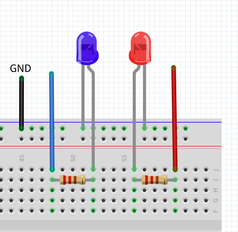
You have the two resistors connected directly to 5V. That is why the are always on.
Move the resistors from the 5V rail connection
As I already mentioned, it's too blurry to read.
Ok I will try that and tell you what will happen
Thank u so muchhh for your help I really appreciate that,I have been trying for a week to find solution the I add it on arduino forrum
Thank u


You did not follow my diagram
I followed what you said and removed the resistor from 5v and it worked as it should
So anything else?
FYI: Just because it works in the tinkercad simulator does not necessarily mean it will work in a real circuit.
Thank u ,for now I just need it to work on tinkercad
Have fun
1 Like
@batoolm, please post a link to the tinkercad project page that describes the desired functionality.
TIA
a7
Sorry but I can’t add the link of tincercad here but I already add photos and the code
And photos of how it worked
This topic was automatically closed 180 days after the last reply. New replies are no longer allowed.