I'm a beginner working on a cable harness tester capable of testing up to 20 lines and display pass/fail on a 20x4 LCD. It will also identify crossed/unidentified pinouts.
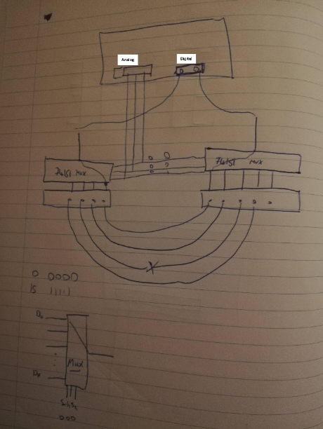
I'm struggling to really understand how to design the circuit. Below is a picture of what I've got so far and I'm unsure if it would work. Someone suggested to use a mux (74151 Mux).
The cable harness will be inserted into the two d subs. The pins of the d subs go to 74151 chips. The chips are connected to the digital I/O pins of the Arduino. The S0, S1, S2 pins of the chips go to a breadboard where the analog pins of the Arduino connect to them.
I'm unsure if this would work at all and I'm not sure what code I would write for this.
Suggest you simply send a series of walking HIGHs down one side of the cable, have a series of LEDs on the other side.
You look at the LEDs to see if they progress in a linear sequence.
larryd:
Suggest you simply send a series of walking HIGHs down one side of the cable, have a series of LEDs on the other side.
You look at the LEDs to see if they progress in a linear sequence.
Unfortunately the results have to be displayed on an LCD. Can I send HIGHs down one side of the cable and code it in such a way that it presents pass/fail on the display?
Mega, so 70 IO available.
Set all with INPUT_PULLUP
Then one by one, set a pin as Output and drive it low. Check the other end that only the 1 matching input is low.
continuity
matched pin
no shorts
Easy to loop thru the pins with a couple of arrays. No shift registers needed.
With only 1 output active at a time, no risk of shorting 2 output pins and damaging them with an active HIGH and an active LOW at the same time if any wires are shorted.
CrossRoads:
Mega, so 70 IO available.
Set all with INPUT_PULLUP
Then one by one, set a pin as Output and drive it low. Check the other end that only the 1 matching input is low.
continuity
matched pin
no shorts
Easy to loop thru the pins with a couple of arrays. No shift registers needed.
With only 1 output active at a time, no risk of shorting 2 output pins and damaging them with an active HIGH and an active LOW at the same time if any wires are shorted.
So could I do that with my current circuit? Thank you.


