Help on (non-working) LM317 constant current circuit

As for Ground or Common, unless we are measuring very tiny voltages at high current, you can use the same ground point to measure all those voltages from.

A voltage is measured from a reference point, and we use a circuit Common which we usually call Ground.

From the numbers you gave, it sounds like your meter's Continuity setting also works as a Diode Check. Most meters are built that way, now.

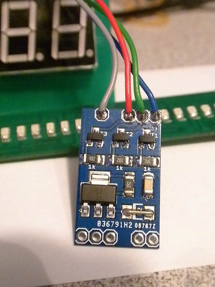
2.) when I take RED prob, put it on Vcc (positive supply voltage).. and touch BLACK probe the BASE (pin 1) on the transistors..

  • (actually I am touching it to the RIGHT side of the resistor, and not directly tot he BASE pin of the transistors)

Each of the leds light up respectively.. (not very bright or anything.. but about the same it did before)
(Im sure changing the 1K resistor values and the 3.9k > 3.9Ohm will help on this a bit though...right?) smiley

Do you mean the black and red probes of your voltmeter? What kind of meter do you have? A typical DMM (digital multimeter) has a resistance of 10M ohm (10 million ohms) and shouldn't cause more than a glimmer of light in the LED, just because that minuscule uA (millionths) of current is being amplified about 100 times by the transistor. Is that what you are seeing? If so, that should mean the transistors are working.

So... with the Arduino disconnected from the LED driver, the LEDs are not lit, correct? If you connect your meter from V+ to the base resistor, that LED lights very dimly, correct?

Ah... with a 220 ohm resistor in place of the 1k, I suggest you also put a 10k (or anything up to about 100k, whatever you have on hand) from the Base to the Emitter/ground.

If I'm reading what you are saying correctly, you have the Arduino switching the wrong way round. Pulling down to light up. Complicated by the fact that tiny bits of leakage current in the transistor may be amplified to light up the LEDs.

I missed that before. You were driving low current 20mA RGB LED before, now with the driver transistors acting as inverters, your code must send a "0" to turn them off, and a "1" to turn them on.

Could you post your code? Don't forget to use the Code tags. Click "Preview", then look for the button labeled with a "#".

polymorph:
When in continuity check on your meter, what does the display say when the leads are not connected to anything, and not touching each other? Is that a blinking "1"? If so, it should be indicating out-of-range, aka Open. In that case, the transistors sound OK.

So when you disconnect the Arduino pins from the base resistors, the LEDs go out? That sounds like the Arduino is the culprit.

With the Arduino powered up but with the LED driver board disconnected, what voltage do you measure on the Arduino pins that are driving the transistors? They should be at 0V or very close to it when the LEDs are supposed to be OFF, and go up to or close to 5V when a given LED is supposed to be ON.

1.) When in 'continuity' mode..
it is a static '1'.. when not touching anything..

2.) When metering the Arduino pins/leads..
I was getting close to +5v.. (not +0v)... and when 'pressing the button'... it would only drop a little bit.. (not down to +0v, only around +4.8xv)

So I opened up the IDE.. and looked to see if I had inadvertantly made the pins HIGH..

I 'did'!!

so I corrected it:

//set-up main barrel led(s)/pins
pinMode(ledR, OUTPUT);
//digitalWrite(ledR, HIGH); //no float
pinMode(ledB, OUTPUT);
//digitalWrite(ledB, HIGH); //no float
pinMode(ledG, OUTPUT);
//digitalWrite(ledG, HIGH); //no float

by commenting out those lines..

then I tried to the original, low powered RGB led (common anode).. and as soon as I powered it up.. all channels in the RGB were on!!! (an odd mix of 'white')

so I removed that.. and plugged in the high powered RGB led (through the constant current board)..

and the leds were "NOT" on this time???..

I tried out the sketch.. and they didnt turn off? (however Im fairly certain that is because the sketch (which initially had them all HIGH on initialization).. turn then HIGH for off)

so now Im a bit confused... about the behavior between the two RGB leds? and the code?

isnt LOW = "ON" for common anode RGB LEDS?

Im mixed up somewhere? lol

for a sanity check..

I checked Radioshack part number to see WHY these two 'common anode' leds behave differently/opposite.

only difference is one is high powered/needs a constant current driver..... and the other was driven directly from Arduino pins

I went back to the sketch.. and reversed my logic:
added a new boolean variable called: commnoAnode

and then for all my digitalWrite() lines.. I did a quick conditional check;

if(commonAnode){
     digitalWrite(currentFireColor, HIGH); 
}else{              
     digitalWrite(currentFireColor, LOW);
}

and NOW the high powered LED sems to work FINE.. and how it should (using the constant current board).. its bright too..

but now.. when I go back to the accent RGB led from RadioShack...

I plug it in.. all leds are ON..
I change to commonAnode = false;
(just to check)
same thing.. all leds are ON.....

HOWEVER... as soon as I press the button (for each color).. they turn off, and then behave normally.. (when commonAnode = false;)

(like they are not initialized correctly or something?)..then one 'used' they work?

IMHO... these two RGB leds should be interchangeable?.. right?

either plug in directly the small/accent RGB led directly..
or replace with t he pins/lines from the constant current board?

So right now..

Im left with a WORKING board.. using the high powered LED.. (YEAH!.. thanks!)..

but I am can not get the small RGB led to work? (and Im confused as to why?)

editL

*DOH!..

I totally missed your other post! :astonished:

"I missed that before. You were driving low current 20mA RGB LED before, now with the driver transistors acting as inverters, your code must send a "0" to turn them off, and a "1" to turn them on."

ok.. this make total sense now! and is the behavior I am getting..

thanks! :slight_smile:

I will change 3.9K value to 3.9Ohm value

That resistor is also looking to small in terms of its power rating.
You're running 320ma through a 3.9ohm resistor, so it's dissipating IIR = 0.4W, so it should be at least a 1/2W resistor.
An 0805 resistor is usually 1/8W, and a 1206 is usually 1/4W.
(Yes, it's really annoying that the 317 CC supply needs a power resistor, instead of having all that power dissipated by the regulator. Grr. Assorted Stepper Motor Drivers are similarly annoying.)

Cool! Problem solved.

As for the 3.9/3.6/3.32 ohm resistor, westfw is correct, you need to calculate power dissipated in it.

1.25V x 0.35A = 440mW

You should always get a resistor -at- -least- double the power rating. That is just good engineering practice. So a 1W resistor will work.

Resistor power ratings go out the window as soon as you put other hot components next to them, put them in a box, lay a wire across them, restrict the air flow, etc. So never run a resistor at close to it's rated power.

thanks!.. yes.. in the end, since switch from DIRECT common anode RGB led.. to a high powered one that was powered by a constant current board, I needed to invert the logic.

Outside of the update/suggestions on a more accurate value LM317 current regulating resistor... and the 1K >> 220ohm value edit... (which I appreciate!...thanks guys!)
the logic was the main issue that is no solved. :slight_smile:

Question:
being a noob/lack of experience.. I rarely give the wattage/power rating of a resistor any thought. (unless noted or am serverly trying regulate the current from a higher voltage or something)..

in THIS situation.. what can be done? or more appropriately.. what SHOULD have been done?

if one is wantign to keep things SMD, and a very small footprint board..

how can you one use 0603/1206 components? Are are there other smaller value components that meet these 1/2-1watt power ratings? or just through type resistors?..etc..

that being said.. and knowing I am using a 0805 (all i could find.. I didnt have anything close in a 1206 footprint like I thought)

A.) if I could order something that would FIT on this current PCB.. to replace the 3.32Ohm resistor.. what would it be?
B.) knowing my application/use for this board/project... how much of a (negative) factor is this against me?
There will be NO color mixing (single color/channel at any given time)
There will be NO long period of time the led is on.. (simple toggle on/off...mSecs)
(its being use as a barrel/muzzle flash.. when the trigger is pulled)

Although not perfect/correct power rating on resistor.. knowing it wont be on for any length of time... thoughts?
can I get away with it? if not.. anything I 'can' use/get to use on the current board?

thanks!

How short is the pulse?

You can integrate power over time, to some degree. If the pulses are very short and the time off long enough, the resistor won't heat up enough to damage it. However, even with long off times, a pulse that is in excess of the power rating can damage or even explode the resistor.

Unfortunately, I cannot tell you exactly what those times would be. If you can tell me in fractions of a second how long an LED will be on, and the minimum time it'll be off...

what can be done? or more appropriately.. what SHOULD have been done?
if one is wantign to keep things SMD, and a very small footprint board..

Yes, it's easy to get into a mindset of "digital logic is low power, LEDs are low power; I don't need to pay any attention to the power ratings of my resistors." And then you notice that resistors keep getting smaller, and even at 40mA through a red LED (~3V drop on the resistor) is more than the 0.1W rating of common resistors...

In this case, it looks like 1W SMT resistors start at about the 2512 package size, and that that would still fit on your PCB if your other smt components went down to 0805. It would be "easy" to put a big SMT resistor on the reverse side of the PCB, but that would make for more difficult assembly. If I had a whole bunch of your existing board, and wasn't TOO space-constrained, I'd be temped to kludge in a TH 1W resistor between the regulator tab and the "common" output; it looks like it would probably fit. Here's a picture illustrating both possibilities:

CCReg.png

I'm liking westfw's solution.

Thanks..

I think I'll just leave these 5 I have as is (or tack on the 1W bridging the regulator tab to the 'common' by the RGB output pads)
there are really no size constrains on where the pcb is being housed.(lots of room) this is all just for fun/stage prop as well so nothing critical depending on it.

but in the future.. I think I'll just re-design the pcb, and use a '2512' 1w resistor.. to make them look a bit nicer. (and remove the diode pads too I suppose) :slight_smile:

*(I have never used a 2512 sized resistor before, so I'll need to order some of those as well) :frowning:

One of the things I noticed in researching this is that 1W SMT resistors are annoyingly expensive ($0.35), compared to 1W TH resistors ($0.09), though the difference gets less dramatic in moderate quantities.

Hey -- glad it's working now. :slight_smile: BTW, because I like optimizing:

if(commonAnode){
     digitalWrite(currentFireColor, HIGH); 
}else{              
     digitalWrite(currentFireColor, LOW);
}

... could be...

// Turn on LED
digitalWrite(currentFireColor, commonAnode);

// Turn off LED
digitalWrite(currentFireColor, !commonAnode);

Basically, if commonAnode == true, it's the same numerical value as HIGH. Same for commonAnode == false and LOW. To turn off the LED, you just invert the value (!commonAnode).

The constants are defined in arduino.h:

#define HIGH 0x1
#define LOW  0x0

#define true 0x1
#define false 0x0

nice....
I wasnt even thinking of use that shortcut/the var like that.. (still really new to Arduino/electronics/C+ in general).. but makes perfect sense.

I have more of a web/web programming background.. where I am/was spoiled about resources/memory..etc..
and even now.. sometimes a shortcut that like would make total sense.. (when Im in here I panic and sometimes forget a lot of the same practices apply in some fashion..logic/theory at least)

so Im taking it one step at a time. :slight_smile: haha

I find that if I have a project or goal in mind.. I can break it up into steps/parts.. and work on them individually and then combine them,.,(instead of random learning...I work through an obstacle to get real world experiences on how to handle it in the future I guess?)

if interested.... this was my last project/goal.. an electronics kit for some guys who like StarWars (cosplay I think?)..
(which you guya have helped me finalize/work through!) so thanks! lol

these pcb's I designed/order/assembled (yeah $17 wal-mart toaster oven! woot!) LOL.. with the help of my Silhouette Cameo Vinyl cutter..I make my own solder paste stencils at home all day long! Cant recommend it enough! (love it!)


*the 3rd board with microSD socket is the 'main' board.. a custom Arduino/Waveshield hybrid

and the last pcb to make up the 'kit' is the constant current board:

and a quick mock-up of it:

however.. based on the feedback.. I have updated things. :slight_smile:

hope this ones better/correct..
*220 resistors
*3.6 Ohm resisotr value (to give full 350mA)
*3.6 Ohm resistors above is a 1-Watt 2512 footprint resistor now
*removed DIODE (pad, wasnt being used anyways)

Here is the resistor I plan on ordering/using in the future..

thanks guys!

westfw:
One of the things I noticed in researching this is that 1W SMT resistors are annoyingly expensive ($0.35), compared to 1W TH resistors ($0.09), though the difference gets less dramatic in moderate quantities.

Needing to use a 1W resistor is a warning sign that the design may not be very good. In this case the issues are that a linear regulator is being used instead of a switching regulator, and a chip intended for regulating voltage is being used to regulate current. I just checked the Farnell site and it shows 22 chips designed for driving LEDs @ 350mA - 12 buck converters, 8 boost converters, and 2 linear current regulators.

I think the LM317 was suggested to me when trying to use a voltage regulator was pointed out to be the wrong apporach.. and I needed to regulate the current

Looking at the LM317 datasheet.. I mirrored the current regulating schematic.

as far as the other stuff.. (if it even fits the current project size..etc.. I dont believe a buck puck even applies here?) is not something I intentionally snubbed.. I just didnt/dont know any better yet.

as mentioned it was my first attempt at a constant current anything.. LOL

As a first attempt, it's not at all bad, and I congratulate you for putting it all together using SMD components.

The LM317 is a very old voltage regulator, and in those days there were few if any constant-current regulator chips made. Circuit boards were larger (no SMD components!) and people were much more willing to waste power. So I guess it was natural for them to show how it could be used as a constant current regulator on the datasheet. I guess the lesson is that not everything shown on datasheets for older devices is now considered good practice.

haha..

fair enough. :slight_smile:

I just dont have a clue if some schematic is outdated or not.. LOL..

I am sorta feeling my way through.. based on the project/goal at hand.. it leads me to learn new things..both in code (like how to use PROGMEM and more so how to retrieve from PROGMEM..lol).. and in hardware. :slight_smile:

thanks!

Nothing wrong with this approach, other than it being inefficient. Sometimes that matters, sometimes it doesn't. Choose your battles. Heck, there are times when a linear reg is not any less wasteful than a switching reg. (Usually low, low current...) There's added complexity to a switching reg, which may not be justified if the wasted heat can be excused. Remember, 1W may not be necessary so much as a design margin.

XL-- you do good work. Those PCBs look fantastic.

thanks!..

I really have a 'low-budget setup'..

Silhouette Cameo Vinyl cutter to cut stencils with:

Vinyl:

Stencils: (use some python script not the Cameo software.. post on Dangerous Prototypes forum)
Atmega328P-AU (SMD)
no swelling of pads before export

now I cut them all the time from some mylar.. or like the ones in the pics, overhead projector transparencies.

**a few home cut stencils and Ive paid for the machine..if I use Pololu or Ryan at (I forget ful name OSharp? something 'er other!) LOL.... as they are around $25-$35 shipped to the door.

some 4$ solder paste from DealExtreme/Ebay... every couple months... and my $17 dollar toaster oven (stock, no sensors, no re-flo signatures..etc)

Keeps me happy and able to prototype/hobby stuff up quickly.

like this project.. lead me to learn about making my first +3.3v Arduino running on INTENRAL clock.. (no external).. and direct 'connect' the SD socket..etc.. for very tiny PCB.. (was for a spiderman web shooter kit/run)
*was supposed to fit a 3D replicas of the watch casing form the TASM movie


toaster re-flow!

I only wish it didnt take 3-4 weeks for PCB's.. :slight_smile: (I am liking Elecrow because of the free color pcb's and still $10 for 10 pcbs)

thanks to you guys who genuinely like this stuff.. and like to talk and teach and educate others. (appreciate it)

HUH.... OK, now I'm looking at getting a vinyl cutter. I have occasional access to one at a nearby FabLab, but it isn't terribly expensive. I picked up a used toaster oven slated to be a reflow oven, as soon as I build the PID for it. (Yeah, I know, but it's a trial run for when I build a PID for my espresso machine.) ]:smiley:

More projects than weekends, unfortunately.