hm ... I think it will be very good if you use such a 10$ 24 MHz 8 channel logic analyser
https://www.ebay.com/itm/253841718379
There is a freeware called PulseView that can read the data from this logic analyser
http://sigrok.org/wiki/Downloads
With this logic analyser you can record how the signals really look like.
2,5ms is medium fast. It would be possible to record this with an arduino too.
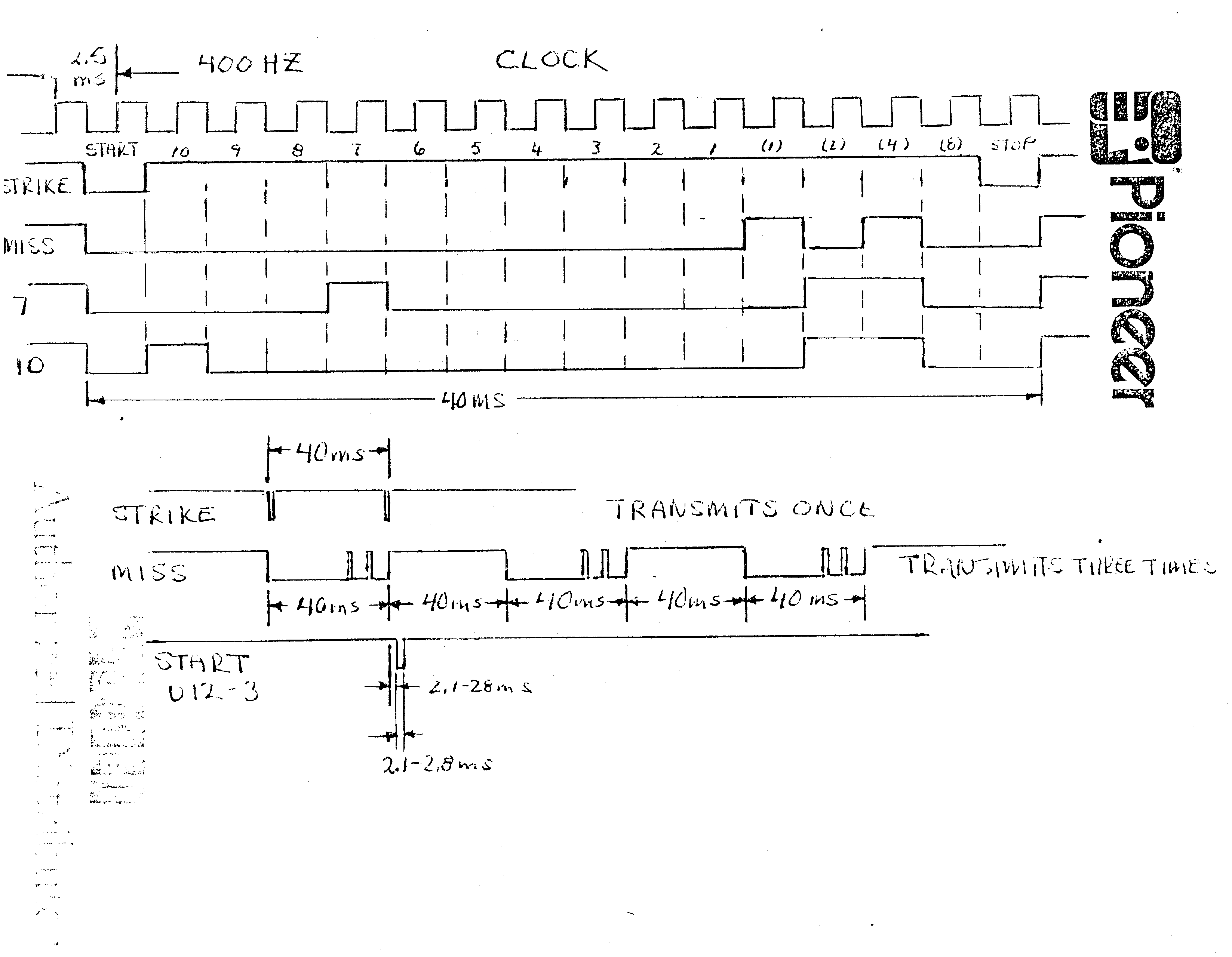
To make things clearer I have added some marks and numbers to the picture
It seems that changes low-HIGH on the dataline start with falling edges of the clock-signal.
before start the dataline is HIGH.
On start the dataline goes low on a falling edge of the clock-signal
if datasignal rises low-HIGH on one of the next 1 to 10 falling edges of the clock-signal this is a pin
If the datasignal stays HIGH for falling-edge 11 to 15 this is a strike
If the datasignal goes HIGH for falling-edge 11
goes low on falling-edge 12
goes HIGH at falling-edge 13
goes low on falling-edge 14
this is a miss
if dataline stays low at falling-edge 11
dataline goes HIGH on falling-edge 12
dataline stays HIGH on falling edge 13
dataline goes low on falling edge 14
this is indicating some pins are fallen
So one idea I have is to use a state-machine
each falling edge of the clock-signal increases the state-variable by 1
1: falling-edge-state
- make snapshot of time with millis()
- increase state-variable by 1
2: wait 500 microseconds
- if 500 microseconds have passed by
-
- read dataline and store bit
-
on falling-edge 11,12,13,14,15
check which conditions are there
to determine strike, miss, or some pins
on falling-edge 16 the dataline should go HIGH again
This concept requires to run the main-loop fast enough to call the state-machine function every 500 microseconds.
So I'm thinking about - additionally - using a timer-interrupt occuring each 250 mircoseconds that does change the state-variable.
But this is pretty fast. I don't know if an arduino can do this so fast.
question: how would you code a 500 microsecond delay inside an interrupt? I'm not sure but inside an ISR microseconds() gets not updated
Or would an approach with storing timestamps when did the next change on the dataline occur be easier?
maybe using two interrupt-pins
first interrupt for the clock-signal falling
second interrupt for the dataline-signal changing
both storing snapshots of microseconds and then analysing the
was it rising or falling and time-differences.
Be the change you want to see in the world
best regards Stefan