Summary:
I need to run a Nema23 stepper motor with 2 momentary switches, and 2 limit switches.
I'm try to accomplish:
Stepper Motor rotate in CW direction when a momentary switch is pressed, go indefinitely.
Hit a limit switch and stop. Back off enough to disengage the switch.
Press Second switch to rotate motor in CCW direction to return to home position which is again detected by second limit switch.
Back off enough to disengage the switch.
Motor has to decelerate when it reaches near to the limit switch. (This is required to avoid hitting the limit switch and damage)
Potentiometer to vary the speed of stepper as per requirement.
The Hardware:
NEMA 23 Stepper (4 wire)
Microstep Driver - SEA5045
24V DC Power Unit
Arduino UNO R3
Limit switches- 2 no’s
Momentary push button/ Toggle switch
My Problem:
I am mechanical engineer, I'm totally new to programming
I saw many other posts and tried to run my hardware but I am not getting success. I saw many of them using AccelStepper, ezButton libraries. But I have no clue what to change to resolve the issues and therefore decide to post a new thread here to get a complete new programme from experts. The hardware connections will be done as per your consideration in programme.
Output I am looking
A complete programme which will run the hardware I mentioned as per my requirement.
If you can add the comments in the programme to understand the function of the codes used it will be of great help (but not compulsory).
Hope that this community will help me to run the setup.
I might have missed some inputs to write code, Pls comment if you need anything, I will provide immediately.
Thank you for going through my requirement.
Regards
Praveen
this seems like a fairly simple program. Once triggered by a switch, a motor can be moved one step at a time until a limit switch become active.
however, it is more common to use a single limit switch and initially "home" the system to determine a "zero" position and then use the motor step count to position the motor and limit it's travel.
once the position of the motor is known, its speed can be controlled to reach a specified position at a desired rate. However, i have no experience with the AccelStepper library that supports accelleration
if the motor just needs to move between 2 end-points, i don't see a need for 2 switches.
on start-up, the motor would "home" by moving in a known direction toward the limit switch and stop. Once "homed", pressing a button could cause the motor to move towards one end-position, knowing the # of steps. pressing the button again would reverse its movement which should return it to the home position with the limit switch active. The code would know the motor position and direction to travel
a pot can be read to determine speed. Presumably the AccelStepper library can decelerate from some specified speed when approaching a desired target position.
Hello @shenolkar. Your inquiry does not look like a request for help, but you want someone to do all the work for you. Better try ask the paid consulting section of the forum.
I have this code which is working for me to go run clockwise and counterclockwise. But there is no limit switch in this program.
The motor will travel from one end to another end : 1500mm. How can I add this travel length in below code?
not sure this is applicable. Your code "steps" the motors while the button is pressed. You presumably release the button when you want the motor to stop or near the end-points.
if you're exactly at an end-point and know the # of steps to reach the other end-point, instead of single-stepping you would step that # of steps. The motor would stop exactly at the other end-point.
when you use a motor library function to specify a # of steps, it doesn't return until that # of steps has been completed. So you would press a button to start the motor and releasing the button wouldn't stop it.
this works because of positioning the motor at the "home" position and setting the motor position to zero at the start of the program.
Commercial CNCs position the limit switches so they can develerate the machine before damage. Better commercial CNCs have two systems of limit switches -- one that directly cuts the power, and another set that provides positioning information to the computer software. The positioning sensors are often set to activate somewhere within the range of travel. Both systems of sensors are placed to avoid damage.
The deceleration is often targeted at the internal numerical idea of limits, rather than the limit switch itself. The device might go through a homing cycle to determine position and numerical limits, then operate to those numerical limits.
so if a limit switch were for example 2" from an end position, a homing function would recognize when it reaches the limit switch and initialize position relative to the swith and during operation, it would always verify its position when it reaches a limit switch.
but position, including end-points would be based on the # of steps and deceleration would be based on steps, not limit switches
seems that an end-point limit switch that cuts off power would act more as a fail-safe rather than prevent damage
The maintenance folks like the power-cutting limit switches to keep the machine from breaking. Marketing might try to advertise the largest possible physical limits of travel. Users might want to know the size of the usable envelope.
Other advantages of not making the physical positioning limit switch be at the actual limits of travel is that you don't have to precisely position the switch actuation at the limit, and that you get different actuation signals depending on the speed you approach the switch. You can handle all the offsets in software. If there's hysteresis in position between making the connection and breaking the connection, or a difference in triggering between moving at minimum speed and moving at high speed, you can program that into the homing process.
You could eyeball a 50mm offset for the physical assembly, and then in software you could start with a conservative 0 or 25mm past the limit for testing and then fine tune it up to maximum travel with a line like
#define X_MIN_POS -52 // mm, measured 2024-08-16
Here's an example of a random bit of Marlin 3d printer configuration where the limit switches are offset from the machine coordinates and within the workspace:
Hi Jackson, thanks for going through my requirement.
I need motor to move back a little so that the limit switch will not remain pressed all the time till I move the motor in reverse direction by pressing the switch.
If you have any suggestion pls let me know.
Hi gcjr, thanks for your efforts. I will try this code and share the feedback.
Do I need to connect the limit switches for this code?
If YES, which pins of Arduino board I need to connect them.
You need to detect the limit switches changing state, from ON to OFF or from OFF to ON, to stop the motor.
Not a limit switch state, ON or OFF.
You can hold a limit switch on physically for as long as you like, that's what they are built for.
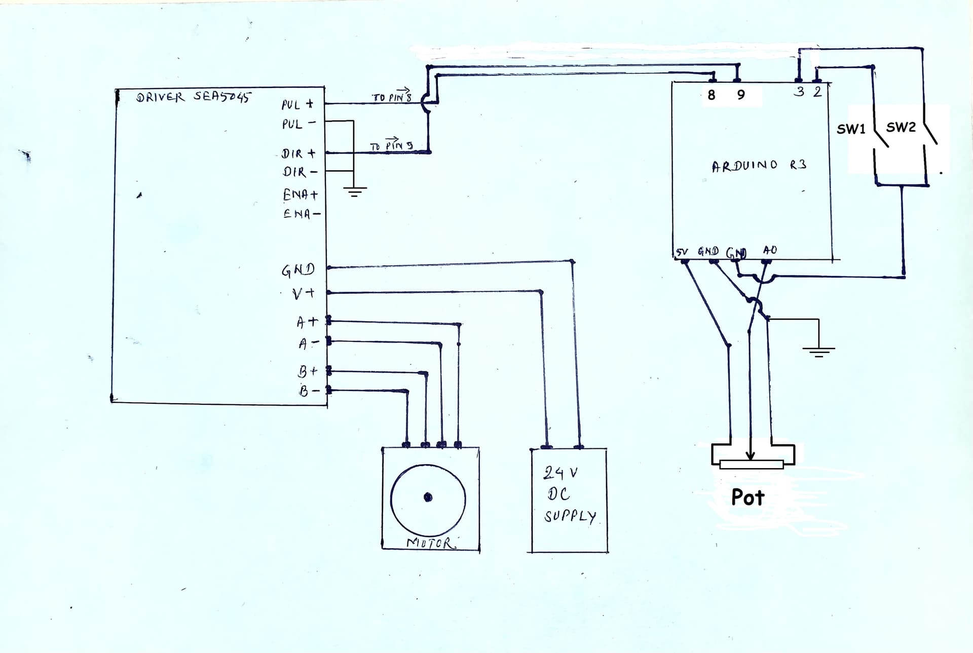
Thanks for the diagram
I have edited you diag, you need gnd connections to the two inputs on the stepper driver.
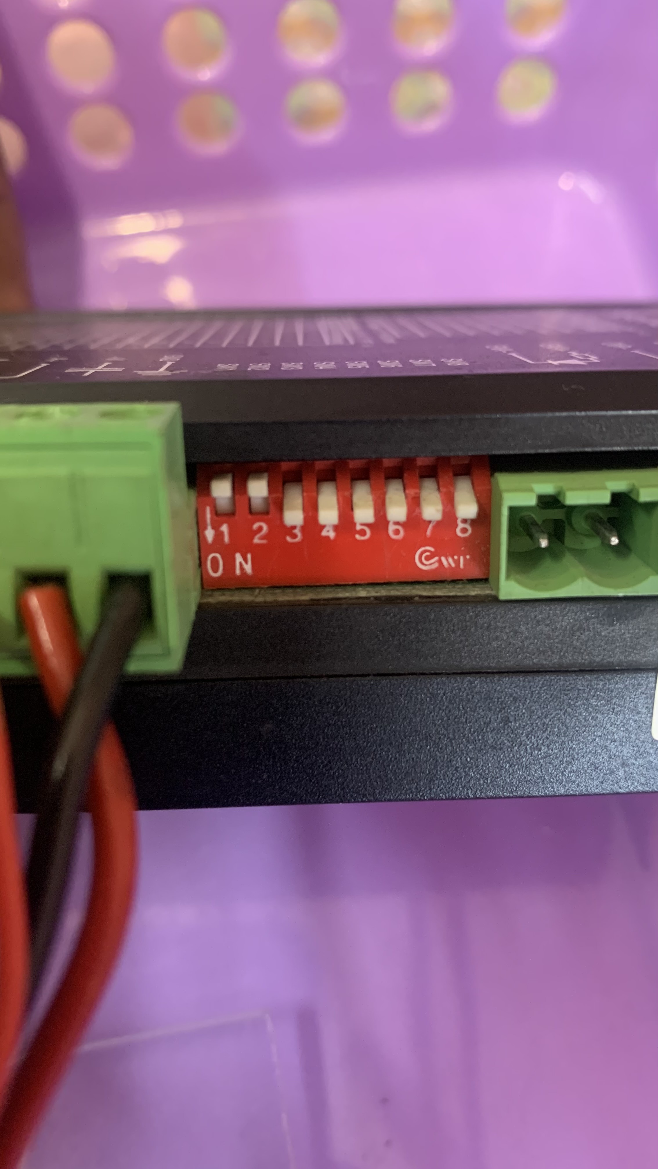
The motor current is set to 2.8 Amps, microsteps to 2 or 400 steps per revolution (for a 200 step motor).
Assuming GT3 means the tooth pitch is 3mm, how many teeth on the pully?