HELP WHIT NRF24L01

Hi guys,

I'm trying to transmit data from an LDR sensor, but I'm not able to capture the data. I only see null values and garbage.

I have already tested some connection examples and they are working, but in my program I cannot find the error! Can you help me?

//TX

#include <SPI.h> 
#include <nRF24L01.h> 
#include <RF24.h>

#define CE_PIN  7
#define CSN_PIN 8

const int pinLDR = A3;
int valorLDR;

const byte endereco[5] = {'R','x','A','A','A'};
RF24 radio(CE_PIN, CSN_PIN);


void setup(){
  Serial.begin(9600); 
  pinMode(pinLDR, INPUT); 
  
  radio.begin(); 
  radio.setDataRate( RF24_250KBPS );
  radio.setRetries(3,5); 
  radio.openWritingPipe(endereco); 
  radio.stopListening(); 

}

void loop(){

  valorLDR = map(analogRead(pinLDR), 1023, 0, 0, 100);
  bool aux;
  aux = radio.write( &valorLDR, sizeof(valorLDR) );


  Serial.print(valorLDR);
  if (aux) {
        Serial.println(" Send");
  }
 
}
//RX

#include <SPI.h>
#include <nRF24L01.h> 
#include <RF24.h> 

int valorLDR;
bool newData = false;

#define CE_PIN  7
#define CSN_PIN 8

const byte endereco[5] = {'R','x','A','A','A'}; 
RF24 radio(CE_PIN, CSN_PIN);

void setup(){
  Serial.begin(9600); 
  Serial.println("Receptor Inicializado");
  radio.begin(); 
  radio.setDataRate( RF24_250KBPS );
  radio.openReadingPipe(1, endereco);
  radio.startListening();
}

void loop(){
  getData();
  showData();

}

void getData() {
    if ( radio.available() ){ 
       radio.read( &valorLDR, sizeof(valorLDR) );
       newData = true;
    }
}

void showData() {
    if (newData == true) {
        Serial.print(valorLDR);
        Serial.println("%");
        newData = false;
    }
}

I tested sending any number, without using the map function, but I also can't.

any help will be appreciated

I loaded your codes to 2 Unos set up with RF24 radios. You are sending data very fast. To slow down the transmissions I use the blink without delay method of timing.

void loop()
{
   static unsigned long timer = 0;
   unsigned long interval = 1000;
   if (millis() - timer >= interval)
   {
      timer = millis();
      valorLDR = map(analogRead(pinLDR), 1023, 0, 0, 100);
      //valorLDR = analogRead(pinLDR);
      bool aux;
      aux = radio.write( &valorLDR, sizeof(valorLDR) );
      Serial.print(valorLDR);
      if (aux)
      {
         Serial.println(" Send");
      }
   }
}

The receiver receives fine and the data that is sent is what is printed in the receiver's serial monitor.

How is the LDR wired? What is the value of the LDR load resistor (the other half of the voltage divider)? Show an example of the received data. Show a schematic of the wiring.

Hi, groundFungus
Thaks for de anser

I made the modification you suggested, however

This is an example of what appears on my RX serial monitor

⸮Receptor Inicializado
0%
0%
0%
0%
0%
0%
0%
0%
0%
0%
0%
0%
0%
0%
0%
0%
0%
0%
0%
0%
0%
0%
0%
10815%
0%
0%
0%
0%
0%
0%
0%
0%
0%
0%
0%
0%
0%
0%
0%
0%
0%
0%
-1%
0%
0%
0%
0%

and this is an example of what appears on my TX serial monitor

66 send
66 send
66 send
66 send
66 send
66 send
66 send
66 send
66 send
66 send
66 send

This is the schematic of the LDR, i am using a 10k resistor
LDR

I don't know if it interferes with anything, however my CE and CSN pins are reversed, if I connect them in the correct position I don't get data, so I write CE 7 but use it 8, CSN 8 but use it 7

What happens when you wire both radios according to the wiring in Robin2's simple rf24 tutorial (CE = 9, CSN = 10 and change the code) ?

Are the RF24 radios the ones with the PCB antenna or the higher power with the external antenna? The high power ones do not like to be too close together (need be a few meters apart).

Do the radios work when running the simple RX and simple TX examples from that tutorial?

The fact that the programs give good results for me says that it is not a software problem, but a hardware one.

Here is the exact code that I am running. Note that I have the CE and CSN to pins 9 and 10 and am using the internal pullup resistor as the load resistor for the LDR.
TX

//TX

#include <SPI.h>
#include <nRF24L01.h>
#include <RF24.h>

#define CE_PIN  9  //7
#define CSN_PIN 10 //8

const int pinLDR = A3;
int valorLDR;

const byte endereco[5] = {'R', 'x', 'A', 'A', 'A'};
RF24 radio(CE_PIN, CSN_PIN);


void setup()
{
   Serial.begin(9600);
   //pinMode(pinLDR, INPUT);
   pinMode(pinLDR, INPUT_PULLUP);
   radio.begin();
   radio.setDataRate( RF24_250KBPS );
   radio.setRetries(3, 5);
   radio.openWritingPipe(endereco);
   radio.stopListening();

}

void loop()
{
   static unsigned long timer = 0;
   unsigned long interval = 1000;
   if (millis() - timer >= interval)
   {
      timer = millis();
      valorLDR = map(analogRead(pinLDR), 1023, 0, 0, 100);
      //valorLDR = analogRead(pinLDR);
      bool aux;
      aux = radio.write( &valorLDR, sizeof(valorLDR) );
      Serial.print(valorLDR);
      if (aux)
      {
         Serial.println(" Send");
      }
   }
}

RX

//RX

#include <SPI.h>
#include <nRF24L01.h>
#include <RF24.h>

int valorLDR;
bool newData = false;

#define CE_PIN 9    // 7
#define CSN_PIN 10  // 8

const byte endereco[5] = {'R', 'x', 'A', 'A', 'A'};
RF24 radio(CE_PIN, CSN_PIN);

void setup()
{
   Serial.begin(9600);
   Serial.println("Receptor Inicializado");
   radio.begin();
   radio.setDataRate( RF24_250KBPS );
   radio.openReadingPipe(1, endereco);
   radio.startListening();
}

void loop()
{
   getData();
   showData();
}

void getData()
{
   if ( radio.available() )
   {
      radio.read( &valorLDR, sizeof(valorLDR) );
      newData = true;
   }
}

void showData()
{
   if (newData == true)
   {
      Serial.print(valorLDR);
      Serial.println("%");
      newData = false;
   }
}

Are the RF24 radios the ones with the PCB antenna or the higher power with the external antenna? The high power ones do not like to be too close together (need be a few meters apart).

They have the external antenna and are close. I pushed them away, to test, I got better results but it didn't work.

What happens when you wire both radios according to the wiring in Robin2's simple rf24 tutorial (CE = 9, CSN = 10 and change the code) ?

Do the radios work when running the simple RX and simple TX examples from that tutorial?

Well, when I use the correct pins it doesn't work, when I reverse the sequence, they work, but with problems -> when I disconnect my Tx, my Rx keeps giving the same message, super fast and without stopping.

Serial TX

SimpleTx Starting
Data Sent Message 0 Acknowledge received
Data Sent Message 1 Acknowledge received
Data Sent Message 2 Acknowledge received
Data Sent Message 3 Acknowledge received
Data Sent Message 4 Acknowledge received
Data Sent Message 5 Acknowledge received

Serial RX

f~⸮fxfx⸮⸮xfx`⸮⸮⸮`f~⸮f⸮SimpleRx Starting
Data received 
Data received 
Data received 
Data received 
Data received 
Data received 
Data received 
Data received 
Data received 
Data received 
Data received 
Data received 
Data received 
Data received 
Data received 
Data received 
Data received 
Data received 
Data received 
Data received 
Data received 
Data received 
Data received 
Data received 
Data received 
Data received 
Data received 
Data received 

The fact that the programs give good results for me says that it is not a software problem, but a hardware one.

I'm also thinking about it, and I'm going crazy already!

I'm using this schematic NRF however with the 9 and 10 inverted

Here is the exact code that I am running. Note that I have the CE and CSN to pins 9 and 10 and am using the internal pullup resistor as the load resistor for the LDR.

Does the internal pull-up resistor make a difference in the transmission? Because I can read the LDR data without a problem.

I thought it could be interference from my router, but I turned it off he didn't get better results.

Could it be a problem with my arduino ports? Are they defective?

I am using the Microsoft Store version 1.8.39.0 of the IDE, with the most updated libraries.

Knowing that it worked there takes a weight off my back, but adds another hahahaha anyway thanks for the dedication to the problem!

9 and 10 are dedicated SPI pins. You might not be able to swap them.

The internal pullup with the LDR has nothing to do with the radio. It is must not how I often wire LDRs. Your LDR wiring is just fine.

I don't know what to make of the CE, CSN wiring. That is just strange. I would say to wire the radios as recommended in Robin2's tutorial.

How far apart are the radios. I have no experience with the high power radios, but Robin2 recommends about 3 meters (9 ft) separation (if memory serves).

Could it be a problem with my arduino ports? Are they defective?

Maybe. Can you try different radios.

One thing. The rf24 radios do not reset when the Arduino is reset. It sometimes helps if you cycle power to the radios after an upload to reset them.

Try the program in Reply #29 in this Simple nRF24L01+ Tutorial

Well I tested it, and got the following answers using CE in 9 CSN in 10:

RX:

CheckConnection Starting

FIRST WITH THE DEFAULT ADDRESSES after power on
  Note that RF24 does NOT reset when Arduino resets - only when power is removed
  If the numbers are mostly 0x00 or 0xff it means that the Arduino is not
     communicating with the nRF24

STATUS		 = 0x0e RX_DR=0 TX_DS=0 MAX_RT=0 RX_P_NO=7 TX_FULL=0
RX_ADDR_P0-1	 = 0xe7e7e7e7e7 0x4141417852
RX_ADDR_P2-5	 = 0xc3 0xc4 0xc5 0xc6
TX_ADDR		 = 0xe7e7e7e7e7
RX_PW_P0-6	 = 0x00 0x20 0x00 0x00 0x00 0x00
EN_AA		 = 0x3f
EN_RXADDR	 = 0x03
RF_CH		 = 0x4c
RF_SETUP	 = 0x07
CONFIG		 = 0x0e
DYNPD/FEATURE	 = 0x00 0x00
Data Rate	 = 1MBPS
Model		 = nRF24L01+
CRC Length	 = 16 bits
PA Power	 = PA_MAX


AND NOW WITH ADDRESS AAAxR  0x41 41 41 78 52   ON P1
 and 250KBPS data rate

STATUS		 = 0x0e RX_DR=0 TX_DS=0 MAX_RT=0 RX_P_NO=7 TX_FULL=0
RX_ADDR_P0-1	 = 0xe7e7e7e7e7 0x4141417852
RX_ADDR_P2-5	 = 0xc3 0xc4 0xc5 0xc6
TX_ADDR		 = 0xe7e7e7e7e7
RX_PW_P0-6	 = 0x00 0x20 0x00 0x00 0x00 0x00
EN_AA		 = 0x3f
EN_RXADDR	 = 0x03
RF_CH		 = 0x4c
RF_SETUP	 = 0x27
CONFIG		 = 0x0e
DYNPD/FEATURE	 = 0x00 0x00
Data Rate	 = 250KBPS
Model		 = nRF24L01+
CRC Length	 = 16 bits
PA Power	 = PA_MAX

TX:

SimpleTx Starting
Data Sent Message 0 Tx Failed

When I reverse CE and CSN:

RX:

CheckConnection Starting

FIRST WITH THE DEFAULT ADDRESSES after power on
  Note that RF24 does NOT reset when Arduino resets - only when power is removed
  If the numbers are mostly 0x00 or 0xff it means that the Arduino is not
     communicating with the nRF24

STATUS		 = 0x00 RX_DR=0 TX_DS=0 MAX_RT=0 RX_P_NO=0 TX_FULL=0
RX_ADDR_P0-1	 = 0x0000000000 0x0000000000
RX_ADDR_P2-5	 = 0x00 0x00 0x00 0x00
TX_ADDR		 = 0x0000000000
RX_PW_P0-6	 = 0x00 0x00 0x00 0x00 0x00 0x00
EN_AA		 = 0x00
EN_RXADDR	 = 0x00
RF_CH		 = 0x00
RF_SETUP	 = 0x00
CONFIG		 = 0x00
DYNPD/FEATURE	 = 0x00 0x00
Data Rate	 = 1MBPS
Model		 = nRF24L01
CRC Length	 = Disabled
PA Power	 = PA_MIN


AND NOW WITH ADDRESS AAAxR  0x41 41 41 78 52   ON P1
 and 250KBPS data rate

STATUS		 = 0x00 RX_DR=0 TX_DS=0 MAX_RT=0 RX_P_NO=0 TX_FULL=0
RX_ADDR_P0-1	 = 0x0000000000 0x0000000000
RX_ADDR_P2-5	 = 0x00 0x00 0x00 0x00
TX_ADDR		 = 0x0000000000
RX_PW_P0-6	 = 0x00 0x00 0x00 0x00 0x00 0x00
EN_AA		 = 0x00
EN_RXADDR	 = 0x00
RF_CH		 = 0x00
RF_SETUP	 = 0x00
CONFIG		 = 0x00
DYNPD/FEATURE	 = 0x00 0x00
Data Rate	 = 1MBPS
Model		 = nRF24L01
CRC Length	 = Disabled
PA Power	 = PA_MIN

TX:

SimpleTx Starting
Data Sent Message 0 Acknowledge received
Data Sent Message 1 Acknowledge received
Data Sent Message 2 Acknowledge received
Data Sent Message 3 Acknowledge received
Data Sent Message 4 Acknowledge received
Data Sent Message 5 Acknowledge received

I don't know how to interpret these exits very well

One thing. The rf24 radios do not reset when the Arduino is reset. It sometimes helps if you cycle power to the radios after an upload to reset them.

Yes, I reset the general power of the Arduino every time I use a new code

Maybe. Can you try different radios.

This is the only way out that I will have haha

Well, I'm going to test it with another arduino and then post if I had any positive results! Thank you so much guys!

To interpret them read the comment.... :o

 If the numbers are mostly 0x00 or 0xff it means that the Arduino is not
     communicating with the nRF24

Well I tested it, and got the following answers using CE in 9 CSN in 10:

This is correct and giving correct debug output, at least on the Rx side.
Most of the registers have their default power on values.

When I reverse CE and CSN:

This is incorrect, at least on the Rx side, since most of the registers are being read as zero.

Data Sent Message 0 Acknowledge received

This is a red herring. It’s a result of all the registers returning zero, and a zero flag indicating a successful Tx.
Some libraries have a function to check for presence of the module. They usually do this by reading a register that has a known non-zero default and checking the result is in range.

Where is the register dump from the Tx side?

I’d just simply add:

  1. The TX sketch in the OP should have a delay(1000) (or better equivalent) in the loop() at least for testing.
  2. Why all the experiments with CE/CSN pins ? Find a reliable pinout for the nrf24l01, viewed from the correct side, Wire the device to the Arduino following a reliable tutorial, and ensure that the sketch matches the the chosen CE/CSN pins.

Thanks to everyone who went out of their way to help me !!!

After reading everything and testing it several times, I managed to make it work!

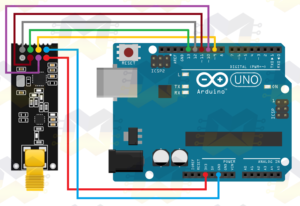
Using CE 9 and CSN 10 - that really wasn't the problem!

And what did I do to work? I just took the Arduino I was using as TX and switch to the RX. Why did it work just by changing the Arduinos? I have no idea, but it worked.

The TX sketch in the OP should have a delay(1000) (or better equivalent) in the loop() at least for testing.

Yes! I added that later, with the function that groundFungus commented

This is a red herring. It's a result of all the registers returning zero, and a zero flag indicating a successful Tx.

After many tests I understood!

Well, I'll leave here the two code that I managed to make it work, who knows, maybe it will help someone in the future!

TX:

#include <Wire.h> 
#include <Adafruit_BMP085.h>
#include "dht.h" 
#include <SPI.h> 
#include <nRF24L01.h> 
#include <RF24.h>

#define CE_PIN  9
#define CSN_PIN 10

Adafruit_BMP085 bmp; 
const int pinoDHT11 = A2; 
const int pinLDR = A3; 
const int pinoSensorChuva = A0;

struct sensores {
  int valorLDR;
  float valorBMP;
  int valorDHTT;
  int valorDHTH;
  int valorCHUVA;
};

sensores mySensores;

dht DHT; //VARIÁVEL DO TIPO DHT

const byte endereco[5] = {'R','x','A','A','A'};
RF24 radio(CE_PIN, CSN_PIN);

void setup(){
  Serial.begin(9600); 
  pinMode(pinLDR, INPUT_PULLUP); 

  if (!bmp.begin()){ 
    Serial.println("Error"); 
    while(1){}
  }
  
  radio.begin(); 
  radio.setDataRate( RF24_250KBPS );
  radio.setRetries(3,5); 
  radio.openWritingPipe(endereco); 
  radio.stopListening(); 

}

void loop(){

   static unsigned long timer = 0;
   unsigned long interval = 5000;
   if (millis() - timer >= interval)
   {
      timer = millis();

      bool aux = false;
      
      mySensores.valorLDR = map(analogRead(pinLDR), 1023, 0, 0, 100);
      Serial.print("LDR:");
      Serial.println(mySensores.valorLDR);

      mySensores.valorBMP = ((bmp.readPressure())/100);
      Serial.print("BMP:");
      Serial.println(mySensores.valorBMP);
      
      DHT.read11(pinoDHT11);
      mySensores.valorDHTT = DHT.temperature;
      Serial.print("DHTT:");
      Serial.println(mySensores.valorDHTT);

      mySensores.valorDHTH = DHT.humidity;
      Serial.print("DHTH:");
      Serial.println(mySensores.valorDHTH);


      mySensores.valorCHUVA = map(analogRead(pinoSensorChuva), 1023, 0, 0, 100);
      Serial.print("CHUVA:");
      Serial.println(mySensores.valorCHUVA);
       
      aux = radio.write( &mySensores, sizeof(mySensores) );
      if (!aux)
      {
         Serial.println("ENVIADO");
         Serial.println("-------------------------------------------");
      }
   }
}

RX:

#include <SPI.h>
#include <nRF24L01.h> 
#include <RF24.h> 

struct sensores {
  int valorLDR;
  int valorBMP;
  int valorDHTT;
  int valorDHTH;
  int valorCHUVA;
};

sensores mySensores;

bool newData = false;

#define CE_PIN  9
#define CSN_PIN 10

const byte endereco[5] = {'R','x','A','A','A'}; 
RF24 radio(CE_PIN, CSN_PIN);

void setup(){
  Serial.begin(9600); 
  Serial.println("Receptor Inicializado");
  radio.begin(); 
  radio.setDataRate( RF24_250KBPS );
  radio.openReadingPipe(1, endereco);
  radio.startListening();
}

void loop(){
  getData();
  showData();

}

void getData() {
    if ( radio.available() ){ 
      radio.read( &mySensores, sizeof(mySensores) );
       newData = true;
    }
}

void showData() {
    if (newData == true) {
        Serial.print("Luz Ambiente: ");
        Serial.print(mySensores.valorLDR);
        Serial.println("%");

        Serial.print("Pressão: ");
        Serial.print(mySensores.valorBMP);
        Serial.println(" hPa");

        Serial.print("Umidade: ");
        Serial.print(mySensores.valorDHTH);
        Serial.print("%");
        Serial.print(" / Temperatura: ");
        Serial.print(mySensores.valorDHTT);
        Serial.println("*C");

        Serial.print("Chuva: ");
        Serial.print(mySensores.valorCHUVA);
        Serial.println("%");

        Serial.println("-----------------------------------");
        newData = false;
    }
}

Some parts are in Portuguese, but I don't think it will hinder understanding!

Thank you all!

tiago_a_s:
When I reverse CE and CSN:

That is a silly thing to do. Just connect them the correct way round.

...R