Come on there are 5 schematics on that page. What are you trying to make.
Edit.
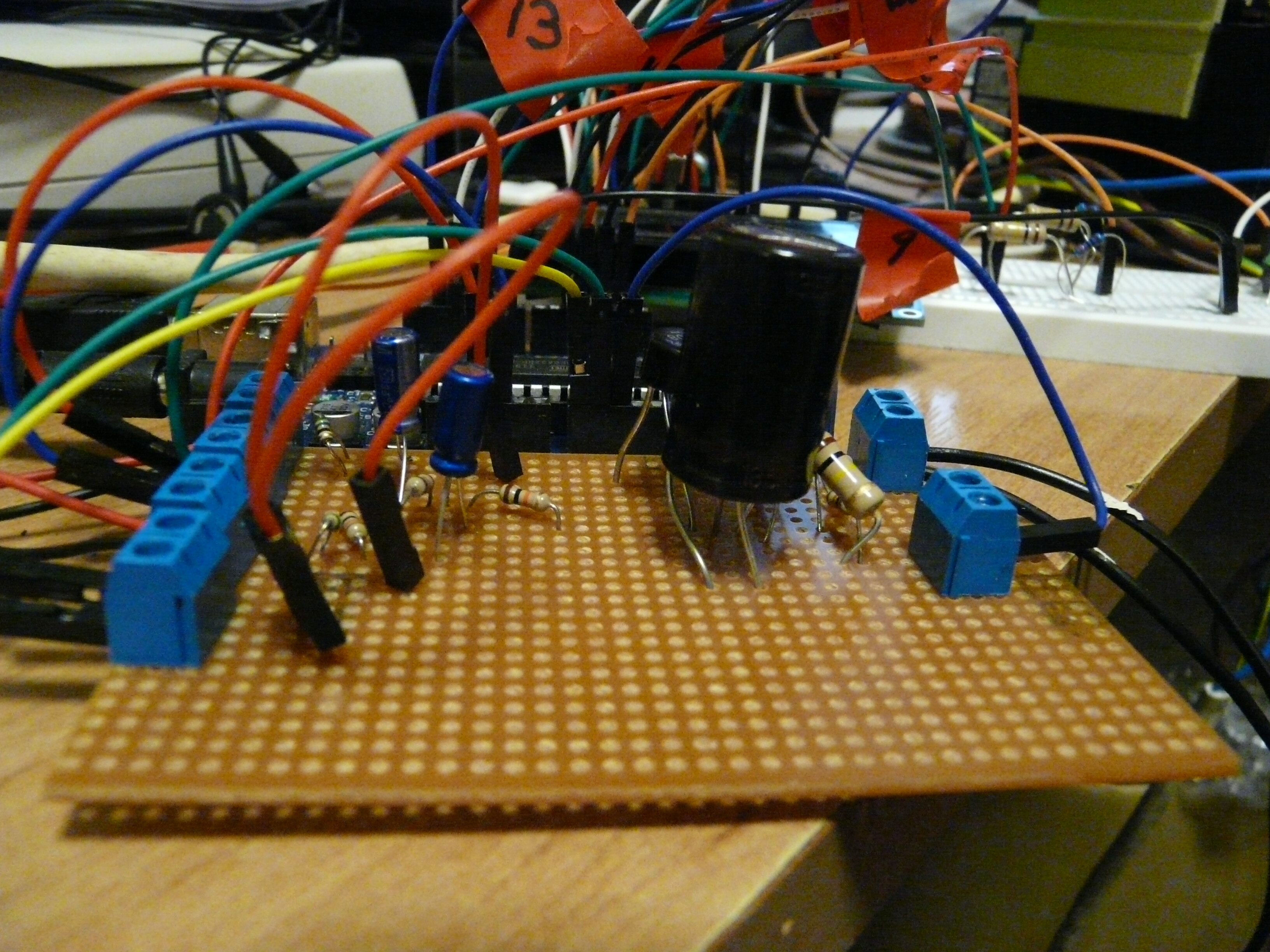
Anyway what ever it is you have it wired up wrong. The only thing that should be connected to the AC output lines is the bridge and the two 1M resistors. From the photo there are three things connected to that line and non of them is a 1M resistor.
There is only one on that page with a bridge rectifier on it. I am making a solar controller which will switch on a triak when there is spare solar power. It consists of 2 current transformers which measure power from the house mains and the other which measures the power being generated from my solar panels. also a 9vac power supply which measures the rms voltage all of the above is working perfectly I am just trying to get the bridge rectifier working so I dont have to get another power supply to feed my arduino.attached is a side on view of the board.
my electronic circuit for the voltage sensing is not the same as that page just the bridge rectifier circuit. my circuit is more like this one How to build an arduino energy monitor | Archived Forum
but with 2 ct's and a bridge rectifier added
Sorry this is not good enough.
I don't need to know what it is like I need to know what it is.
That is the only way I can see if you have made an error in designing it or an error in implementing the design.
If you do not provide the correct information there is no way we can tell why you are getting results that frankly do not make sense.
You can not be seeing the voltages you see with the circuit as you describe. So something has to be wrong, all I am trying to do is to find out what. But in order to do this I need cooperation from you, if you are not prepared to give it then there is no use in perusing this any further.
Fine, just be sure to specify that only people with ESP need apply to help you.
If you look back on the thread you will notice I became grumpy at the same time you started to refuse to cooperate.
I read this tread, energy monitor is interesting project.
First. We are not there to see what you did... example : bad wirings, bad parts, wrong reading... etc...
So it is difficult for us to see and trying to help.
Second : I did a few PSU with : A transformer, a bridge and a cap. A lots of DIY and I work at Tectrol Inc. for 4 years in the 1990's.
Now... Here what I do when I design a PSU.
Measure the transformer being use. With no load, just AC in and measured V out.
The Transformer can be any garbage wall wart being found in dumpster or people's garbages. ( I have a lots. I even have a 220 model wall wart. Or brand new.
You know what V Out, connect secondary leads at AC input of the bridge rectifier.
Connect a electrolitic cap of 1000 uF to 4700 uF. Check polarity and the voltage rated has to BE DOUBLE of the voltage measure of the transformer X square root of 2. example : 6.3 V ac --> 8.9 V ac peak. rated cap : 35 V is OK.
Measure the DC output with no load. It should match the calculation.
Connect the output of the unregulated voltage to a Voltage regulator chip. Example : 7805 with the proper inptu and output cap. - In 10 uF, 0.1 uF - Out - 0.1 uF , 10 uF
I will do all that, do it safely and double check my work.
Fine, just be sure to specify that only people with ESP need apply to help you.
My guess... what you connect is : A voltage doubler. Make sense to me.
I honestly cant tell what connects to what, its just components on a board, for all I know its connected directly to mains and is shorted out
draw out exactly what you have on paper, a rectifier is a pretty simple device (its 4 diodes in a circle), you have 2 leads marked ~ for ac input, 1 + and 1 - for dc, back up, disconnect everything to that point and see what you get with a meter. you should put in X voltage AC and get Y voltage DC out of the single item ( y = X - drop in diodes, which wont be a ton)
guess work and esp on which random diagram, and how you interpreted it is totally useless cause you have obviously done something wrong.
There is only one on that page with a bridge rectifier on it.
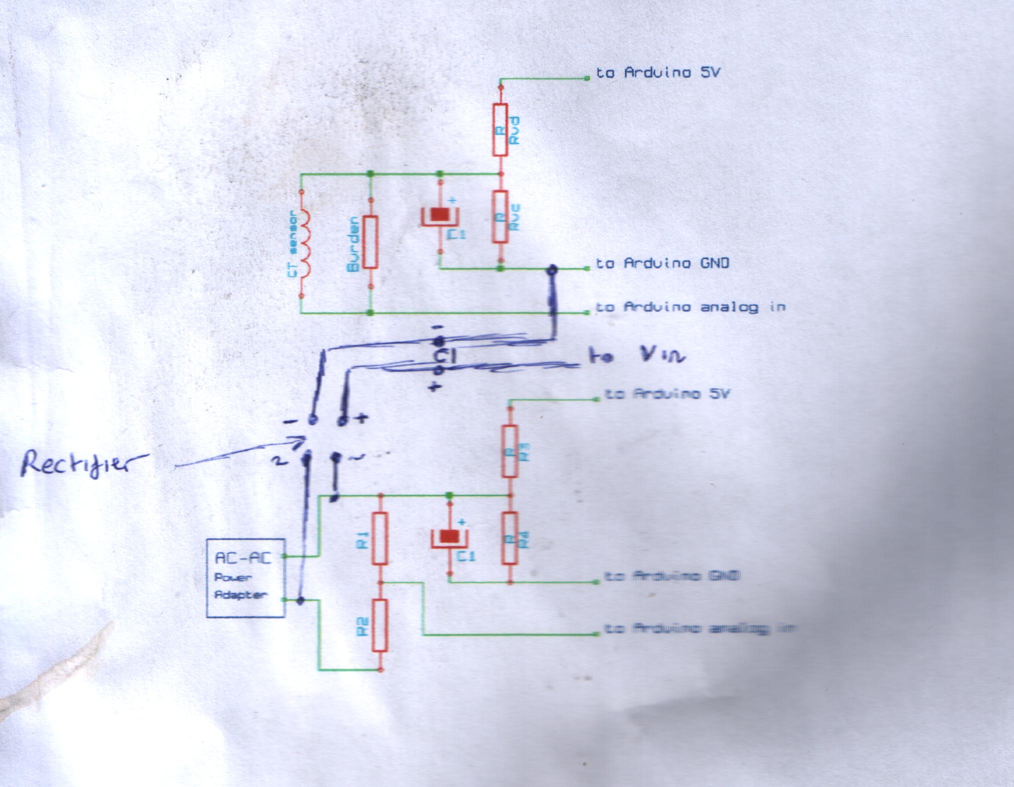
attached is a scan of my circuit. I have checked again with a different meter and I am still getting 19v dc. someone told me that I will get a high voltage output when there is no load connected, but should it be that high? and he told me to put a voltage regulator in the circuit. does the arduino have its own built in regulator and will handle up to 20v dc?
madmurg:
attached is a scan of my circuit. I have checked again with a different meter and I am still getting 19v dc. someone told me that I will get a high voltage output when there is no load connected, but should it be that high? and he told me to put a voltage regulator in the circuit. does the arduino have its own built in regulator and will handle up to 20v dc?
The problem is the R1, R2, R3, R4, and C1 components in the lower part of that drawing. What is the purpose of those components? I suspect that C1 is acting like a voltage multiplier adding to the output voltage of you rectifier circuit on the top part of the drawing. Temporaily remove those components from the circuit and tell us then what you measure on the DC output side of the rectifier.
The step down voltage divider scales the AC voltage coming from the voltage adapter down from 9V to around 1V peak-peak.
The resistors R3 and R4 form a voltage divider that outputs a voltage at half the Arduino supply voltage of 5V. This voltage biases the AC voltage produced by the AC adapter and burden resistor by 2.5V, needed because the Arduino analog input channel requires a positive voltage.
madmurg:
The circuit is for a voltage measurement circuit
The step down voltage divider scales the AC voltage coming from the voltage adapter down from 9V to around 1V peak-peak.
The resistors R3 and R4 form a voltage divider that outputs a voltage at half the Arduino supply voltage of 5V. This voltage biases the AC voltage produced by the AC adapter and burden resistor by 2.5V, needed because the Arduino analog input channel requires a positive voltage.
Voltage at analog input = Bias Voltage + VsensV
As I said remove those components from the circuit temporarily and report back the rectifier voltage then measured.
I am not going to desolder all of these components as a newbie to electronics it took me about a week to get them working right. it was just an after thought that I decided to fit the retifier. I think I might just get a separate dc adapter and power the arduino that way.
madmurg:
I am not going to desolder all of these components as a newbie to electronics it took me about a week to get them working right. it was just an after thought that I decided to fit the retifier. I think I might just get a separate dc adapter and power the arduino that way.
Suit yourself. I just depends on if you want to learn something or just get a copied design to work, your choice.
Sorry you don't want to take advice from those who are not new to electronics.
Of course you do not have to accept our advice, which by the way you did ask for, that is up to you.
Still for what it's worth ............
In the bottom part of your circuit you have an electrolytic capacitor.
It shows that you know little about electronics because these capacitors ( unless they are very, very special ones ) do not like being connected to A.C.
Much as you may not like it for me to tell you this it could be DANGEROUS as it could easily explode.
Connecting this part of the circuit to your arduino will apply 50 times or 60 times per second ( depending on where you live ) reverse voltage to the arduino which will likely destroy it.