Ok, now I have a new problem. I've been told to create a new post and to NOT create a new post if it's the same project, but a different problem....so I'm not sure which is most appropriate. So forgive me if this isn't the right protocol.
Regarding the project above. All functions as it is supposed to now; however, randomly the motors will start turning (typically if I plug something into electrical plugs). Earlier it did it when I touched a USB fitting plugged into the arduino. What would cause this and how can I fix it? I'm afraid the table will randomly start moving when I'm not in the room. Any help is appreciated.
See this and check if any of it applies.
It could also be an issue with your house wiring or an appliance that causes a surge.
maybe try move the whole project to another area of the house ?
@Ballscrewbob Thank you. Looking through that post could apply. I've got a few concerns. My CNC has it's own 24v power supply to control it's steppers/drivers etc. I have the controls for the table on it's own 24v power supply. Both of these are connected to 120v for the supply. I also have my arduino being powered by a 5v power brick. None of the grounds between those 3 devices are shared. Could that be the issue?
OK I have some homebrew CNC's here with multiple power supplies.
YES they all share a COMMON GROUND.
Not sure how your CNC is built but here I also have some ground bonding cables between some parts of the machine.
My table has a lead that goes from it to the frame.
My Z-axis also has a lead that goes from it to the carriage.
Then the Carriage has a lead to the frame.
Frame also shares a common ground.
That has helped to combat static here which I get a lot during the transition from winter to spring.
Ok, let me ask you another question. Can I join the V- of the two power supplies without issue? What about also bonding the arduino ground to the same spot as the two power supplies? I'm getting some really odd behavior. I put a switch in between the power for the drivers for the steppers (for the table). If I turn it off and then back on, the table starts going down (I haven't seen it go up automatically yet). I can stop it via my "stop" button, but sometimes it will go again sometimes it won't. If I switch the toggle I put in between the drivers and power off and then on again, the table will start moving again without me hitting "up" or "down" buttons. I totally disconnected the "down" button and it will still go down when powering on (sometimes very fast). I also totally disconnected the power supply to the CNC and it still does it. Could it simply be that I need to bond the ground between the arduino and the 24v power supply?
Here I have a 5 volt, 12 volt, 24 volt and all the - sides are commoned.
The Arduino shares that common too.
As do the 12v fans I have installed and the 5 volt relay board for the air assist pump on the laser.
Terminal strips can be used if you want to simplify things.
Here is an approximation of my setup.

Thanks again. After I posted my questions, I tied the grounds together on my various sources and the arduino. That didn't help....but I think I figured out what the problem was. I had put a relay with a 24v coil inline so that I could cut power to the stepper drivers via a toggle switch. It looks like somehow that relay was "leaking" or causing some other sort of problem. I measured the voltage on the output of my pulse output of the arduino. If the motors were stopped and I turned off the switch...that output would be dead, but when I switched the switch back on, it would output 2v....triggering the drivers to tell the steppers to start to turn. I have no idea why that was happening. I'd like a way to cut power to the drivers when the table isn't in operation just as an additional layer of safety. Any suggestions?
Relays can cause spikes.
An SSR (Solid State Relay) offers a better choice.
You could also employ a kill switch / E-stop on the output of the supply that feeds the motors.
Also note that limit switches will always benefit from filters attached and shielded wire as these too can cause glitches.
Not sure what you are using in that regards ?
but when I switched the switch back on, it would output 2v....triggering the drivers to tell the steppers to start to turn.
Can you please provide your latest schematic and code.
I may take that advice and just install a e-stop and be done with that part. I have a couple of SSRs, but not with the correct coil voltage.
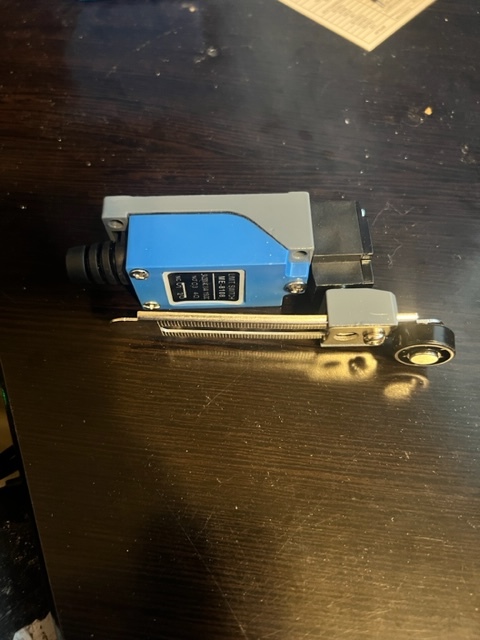
Regarding the filters on the limit switches, can you elaborate on what you mean? I'm just using the type in the attached picture. I'm using shielded 16ga, 2 conductor security wire. I don't have them installed yet. I'm 3d printing a flag to trigger them.
code is the same as above. The schematic is back to how it was above as well. I tried to add a relay inline to kill stepper drivers to the table when not in use, but that didn't work. I just remembered my stepper drivers have an "enable" pin. I might be able to take advantage of that.
This is the most common arrangement but can be problematic.
This is the preferred method.
I'm sorry @Ballscrewbob , I should clarify......my CNC is a Longmill by Sienci labs. It comes with it's own controller, drivers, and it uses prox sensors for the directional maxes. It is GRBL based though. All my questions are actually pertaining to the table and not the actual CNC.I have limit switches for when the table is in the "up" position, and then also when it's in the "down" position. I just remembered also, that my stepper drivers have an "enable" input. I may look into that further regarding killing the drivers when not in use.
1 Like
If this is the code in Post #5 then "triggering the drivers to tell the steppers to start to turn" means you are entering the MOVING state. This can only happen when one of the input switches reads LOW.
How does the in line relay create this situation?
Yessir, I understand. And I have no idea how/why that was happening. As I stated above. When the relay was engaged, the arduino was changing from "low" to "high" on the "step" pin causing the motors to turn. I was using the relay to pass the ground on to the drivers to turn them on. I can only guess that the relay was leaking/backfeeding a ground signal somehow, triggering the output on the arduino as if a button had been pressed.
OK, progress. I'm hoping someone has some suggestions. I was able to figure out what was causing my problem (at least partially). @cattledog had a good point. It didn't make sense that my steppers were starting/stopping/reversing automatically yet they worked fine on the breadboard test setup. Like I said at the first of this post....I'm sending the signals through a CAT6 cable with a RJ45 breakout board on each end (picture attached). I took the button assembly and just ran 6-8" jumpers directly into the arduino and it works perfectly as it should. I assume I'm getting some induced noise in the lines (I should mention that the CAT6 cable is in a loom with a 120v power wire also). The electronics are under the table. I can't climb on the floor every time I need to operate the table, so I need the longer wire. Any suggestions as to how I prevent the problems I'm having?
Signal wires should always be separated from higher voltage ones.
In industrial applications they often have a steel separator plate on the gantry runs.
Failing that shielded versions of CAT / ETHERNET cable can be had.
Have also used thin steel tube here to good effect.
Aren't you just full of good news  I really didn't want to pull all that down and re-run it. I actually thought about it after I ran the power with the signal wires....that it probably wasn't a great idea. Do you think some "debouncing" code added would help...or should I just not try to "tap dance" around my screw up and just re-route the wires?
LOL sorry about that 
If they are used as proper CAT / ETHERNET cables I would bite the bullet.
If however you are using them for other purposes you could do a little filtering at one or both ends. as shown in the pics.
Some form of debounce might help and is you are using GRBL there is already a parameter for you to play with.
See $26 as that is the debounce figure, mine is 250.