Good Morning
This is my first play with Arduino
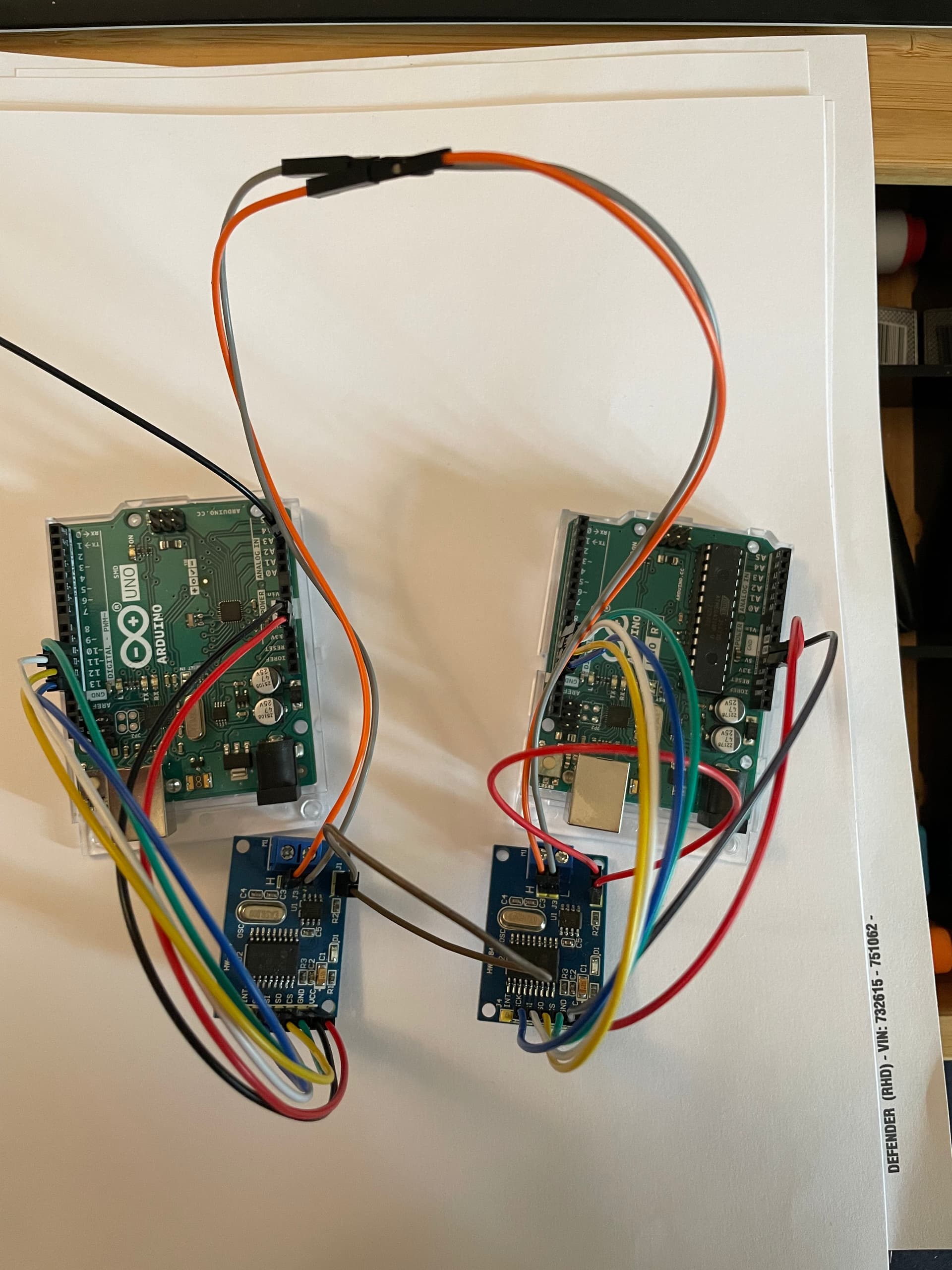
I have set up to Uno,s each with a CAN can shield attached
linking the two can boards High and Low and bridging both 120 ohm resistors
I can send a can message from one and receive it on the other.
however when I try to read this messed using a PEAK i don't see the message.
I have tried connecting it in to my network and sending a known message but the controller does not respond **(if is send the message from Peak the controller responds)
I have checked the KBS on both Peak and the UNO Bothe running at 250
does anyone have any ideas why I can see the message on the system
can you give a link to the PEAK documentation or at least a description?
what CAN shield are you using?
Have you a multimeter? if so what are the voltages on the CAN_H and CAN_L lines?
download your code (using code tags </>)
I find it useful when dubugging CAN system to have a USB-CAN dongle which can plug into a PC to view traffic
Thank you for reply Horace
The Peak is a USB Can Dongal (this is where I can't see the message sent)

The image is what I have linked up
Please see coding of sending msg
(I can see the output on the second unit on the on screen monitor)
// CAN Send Example
//

#include <mcp_can.h>
#include <SPI.h>

MCP_CAN CAN0(10);     // Set CS to pin 10
//-------------------------------------------------------------------

int oillight = A3; // Oil Light Input to analog pin A3
                    // outside leads to ground or open
int oval = 0;  // variable to store the value read


//-------------------------------------------------------------------


void setup()
{
//-------------------------------------------------------------------
pinMode(A3,INPUT_PULLUP); // made reading when earthed 14
//-------------------------------------------------------------------
  Serial.begin(115200);

  // Initialize MCP2515 running at 16MHz with a baudrate of 500kb/s and the masks and filters disabled.
  if(CAN0.begin(MCP_ANY, CAN_500KBPS, MCP_16MHZ) == CAN_OK) Serial.println("MCP2515 Initialized Successfully!");
  else Serial.println("Error Initializing MCP2515...");

  CAN0.setMode(MCP_NORMAL);   // Change to normal mode to allow messages to be transmitted
}


byte data[8] = {0x10, 0x10, 0x10, 0x10, 0x10, 0x10, 0x10, 0x10};


void loop(){

   oval = analogRead(oillight);  // read the input pin A3
  Serial.println(oval);          // debug value


if(oval <20){  //increase to <20 if using pullup

      Serial.println("Oil Light On");

   } else {
      Serial.println("Oil Light Off");
   }


  // send data:  ID = 0x100, Standard CAN Frame, Data length = 8 bytes, 'data' = array of data bytes to send
  byte sndStat = CAN0.sendMsgBuf(0x100, 0, 8, data);
////----------


  if(sndStat == CAN_OK){
    Serial.println("Message Sent Successfully!");
  } else {
    Serial.println("Error Sending Message...");
  }
  delay(1000);   // send data per 100ms
}

/*********************************************************************************************************
  END FILE
*********************************************************************************************************/
is the UNO to UNO working OK with the PEAK attached?
I assume nothing is displayed on PCAN-VIEW?
are you sure your CAN modules are 16MHz? perhaps try 8Mhz?
When I did it I had to connect the INT\ to pin 2 or it would not work. I had problems initially with the analyzer reading the bus but when I changed the code to the correct crystal it worked great.
Thank you so much Horace
I changed the code to 8Mhz and it worked.
I can now see the message on the Peak-View.
I thought the code referred to the Uno board (Which is running 16Mhz)
So many Many thanks
As I said in my first post Im just starting out on this project, so much more e learning for me to do.
This topic was automatically closed 180 days after the last reply. New replies are no longer allowed.