Help with controling Pneumatic Control Valves

Hello Everybody!
First,I appoligise if I maybe can't explain everything in English correct....I'm from Sweden and will do my best to explain my "problem"
I'm 58 years old,and totaly new to Arduino,are a machine technician,and familiar with pneumatics,sensors and similar,but newbie to programing.

But I really want to learn,are curious and like to learn new things!

I will try to explain my project,appologise if it's a long topic!
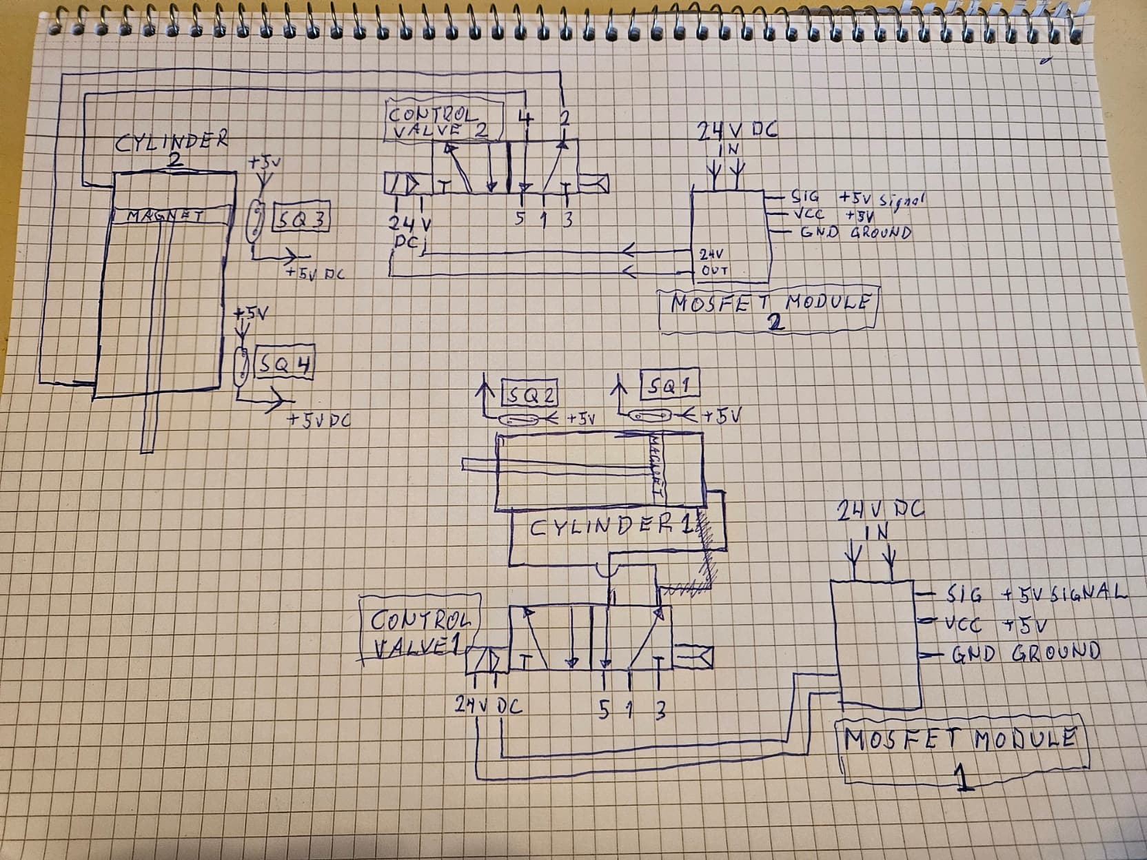
Attach a simple schematics how everything will be connected,hope it will show my intention.

First,the thing I want the "machine" to do:

In normal inactive state,both cylinders are retracted,and control valves are without signal.
SQ#1 and SQ#3 gives a +5vDC outsignal.
When it start,(button,power up or similar,no preference how to start the sequence),cylinder #1 should extend to end,(SQ#2 gives a +5v signal),and retract directly.
When cylinder #1 retracts,Cylinder #2 should extend to end and retract directly.
(SQ#3 and SQ#4 send a +5vDC outsignal when retracted and extended.)

Then cylinder #1 should extend and retract again,and cylinder #2 again....on and on constantly until I power down,flip a switch or similar.

Start and stop can be Power down the module or by a switch,no need for advanced solutions to start and stop,main thing is to get a safe loop to run this sequense for say 4-500 cycles.

IF possible can it be done in some way when using the SQ1-4 for signals to the Control Valves?
Say cylinder #2 can not extend before cylinder #1 have retracted?
The speed of the cylinders are not critical,they can run slow if neccesary,that will be controled by the pneumatic system.

The parts that will be used:
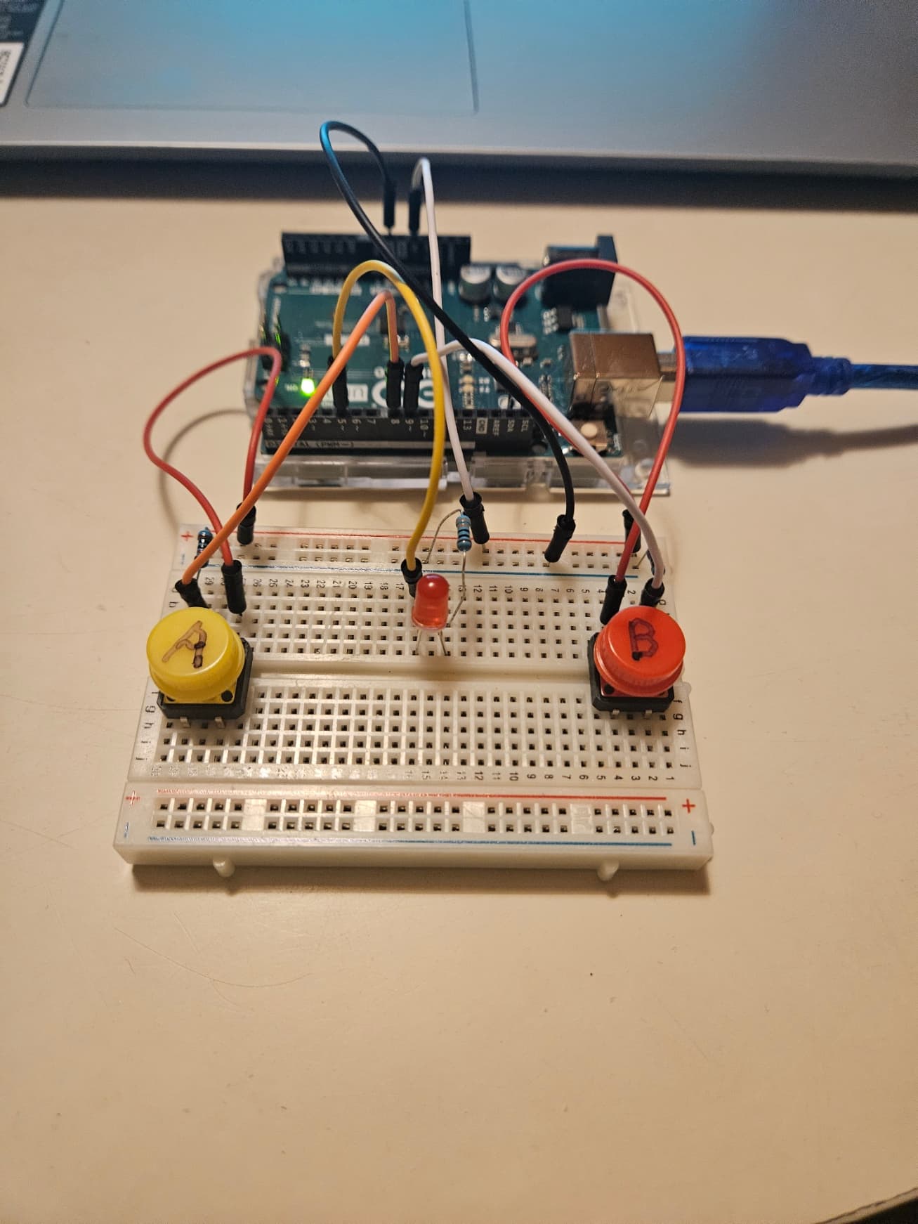
Arduino REV3 SMD Board.
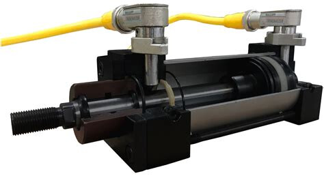
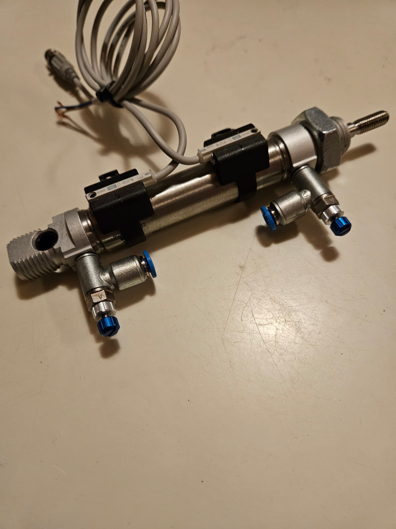
Festo pneumatic cylinders.
Festo CPE14-M1BH-5L-QS-8 control valves.(24VDC/1,28W Coil)
SMC D-M9PW cylinder proximity switches.(5VDC PNP "Reed type" switch,10mA current draw)
24VDC Switched Power supply for pneumatic control valves.
The 5VDC supply needed for the SQ:s and Mosfet I hope to take from the Arduion,if possible?

When I have done other things like this,I always used "mechanical switches",or control everything with pneumatic switches.....it works,but "bulky" and not up to modern standard.
I really want to learn to control things with "computers",it's fun and more up to modern standard!!

Ihope to get some advice how to make a simple and functionable sketch for this,and try to learn what I'm doing during the programing sequense.
If I can do this and learn and understand what the program is doing,I maybe can take a new approach to when I build things in my home workshop.

Really greatful and very Thankful for any help or pointers in the right direction,just remember...I'm old and a newbie,so if it's simple and just basic function should I be very greatful.
Best Regards
Anders from Sweden.

Anders, can you please post links to the specs of the control valves and proximity switches.

It is not clear whether MOSFET modules or H-bridge modules will be needed to control the valves.

The description of the proximity switches is ambiguous because PNP implies perhaps a Hall-effect sensor but "Reed type" implies a magnetic mechanical reed switch.

Hi Paul!!
Thanks for Your answer!
The "reed" are maybe misleading from me,Hall sensor are maybe correct description.
Here are some links to the Controlvalve and swithes:

Solenoid valve CPE14-M1BH-5L-QS-8 (festo.com)

D-xS-OMJ0004.pdf (smcpneumatics.com)
(Page 24 are the specs.)

The Mosfet Module I have are rated for max 5A output,(1A without heatsink)
Here are links to them:

744989_87045_manual_en.pdf (kjell.com)

No Title (kjell.com)

I also have "normal relays" for Arduino if they are "better" or more useful in this application then the Mosfet?

Hope this will help!
And THank You for Your interest to assist,very apprichiated!!

BTW,due to the timedifference and my work,are I not maybe so quick to answer,but will check as often I possibly can.

Regards
Anders.

You are not old. I am 84 and that is old!
You are familiar with pneumatic and hydraulic devices and should recall that they all take time to operate. That time is an eternity for your Arduino. Some type of feedback needs to be in your project so the Arduino will know exactly when some operation you describe, has been completed.
Even the old plastic injection machine I once owned had feedback for all operations and no computer was involved.

Wow!
Well,that's impressive and give me hope that it's not to late to learn this!!
Yes,the Arduino is quicker,than the cylinders for sure,that's why I maybe hope the switches can be the parts controling the movement.....the next cylinder sequense will not happen before the "homeswitch" on the other cylinder gives signal.

But as I said...I know how it should work,and can fix it with limitswitches and relays,but that's no challenge,really want to learn this and maybe have some fun building things Arduinocontroled!
Love to build things,and have a quite big workshop at home with lathe,millingmachines,grinding machines,welding equipment and so on.....the mechanical parts are easy,but the "computing" are a new thing to implement to my hobby!!
Regards
Anders.

But you still need all that stuff so the Arduino can do the controlling. Without that stuff, the Arduino is blind!

Ok,so the proximity switches on the cylinders are not enough to control the sequense?
Must I also put e.g inductive sensors on the "moving parts" that the cylinder moves,both extend and retracted?

In that case it starts to be a lot of sensors that the Arduino needs,then it's maybe easier to just use pneumatic limitswitches that switches the controlvalves,and some other pneumatic valves....accumulators,pilotcontroled valves,"And/Or-valves" and so on.

I can make it work pneumatical,but wanted to use a e.g Arduino to learn something new,but if I need sensors everywhere,and several sensors for one simple movement it's maybe overkill?
Anders.

All depends on what you are using for switches and where they are placed. All mechanical switches will give false connection indication if you are testing for a switch closing. The contacts are always spring loaded and will bounce. If your limit switch just opens, then any bounce can be ignored. The Arduino is so fast it will detect bouncing switch contacts. So, beware when you write the program.

Similar to one of these?

image

image

Switches are obviously placed at the end of the cylinder/piston/rod/actuator travel (drawing above). Switch bounces should be easy to manage considering the Arduino workload.

Not to mention the switches Anders suggested have Hysteresis (overkill switches for a home project in my opinion).

You only need to connect the switches as they should. NPN D-M9N(E) or D-M9N(E)V should be OK with a Pull-up resistor (connected to 5V). With a max 100 µA leakage current, a 10K resistor should be OK.

If using the PNP D-M9P(E) D-M9P(E)V, a 10K pull-down (connected to the ground) will do.

As your project is an easy one, read some entry level tutorials (buttons, delays, state machine) to get you started.

Yes Doug.
It's similar,the photo are of "Cylinder #1" that will be used,same switches on both cylinders.
#1 are a small cylinder with 60mm stroke,#2 are bigger with 80mm stroke.
But same switches on both cylinders.

Anders.

Thank You for the comment,I will read about the State Machine,looks like it's the way I should go.
Thank You!
Anders.

Hello andersjb

Please post the datasheet to see details.

Hi Paul.
If You mean datasheets for the components,the links are in post #3 above.
If it's another info You need,please let me know and I will try to answer the best I can.
Thanks!
Anders

1 Like

Don't forget to add a freewheel diode in parallel with every electromagnetic actuator you connect (relays or those Festo CPE14-M1BH-5L-QS-8 control valves).

The cathode (generally marked with a ring) should be connected to the positive side as shown here.

Any 1N400x should do.

Hi.
I will do that,Thank You!
Anders.

Hi again...
Did a very basic sketch and put it together on the board.....2 buttons that simulates the cylinderswitches,and a LED that simulates the relay for the pneumatic valve.
Did this to try to learn the basic,and get a function of the valve get a signal so the cylinder extend and retracts by the signal from the switches.

Very simple sketch,and no "safety",but it should work this way.

Now just try to figure out how to duplicate this,and let the other cylinder and valveloop to be controlled by the first loop.
Did plenty of misses before it worked....casesensitive,brackets and how to designate each pin....new world to me,but hopefully I will learn more!


```cpp
int switchA = 8;
int switchB = 9;
int relay = 5;

void setup() {
  pinMode(relay, OUTPUT); //pneumatic valve via relay
  pinMode(switchA, INPUT); //cylinderswith retracted
  pinMode(switchB, INPUT); //cylinderswitch extended
  
}

void loop() {

  if (digitalRead(switchA) == HIGH)
  {
    digitalWrite(relay, HIGH);
  }
  if (digitalRead(switchB) == HIGH)
  {
  digitalWrite(relay, LOW);
  
  }
  

}

Anders.

That's an excellent start !

The way it is written, the digitalWrite(relay, HIGH) instruction is executed over and over again as long as the switch is pressed.

Next step could be to execute it only once. To do that, you can read the relay (yes, outputs can be read too) and write it only if it's LOW using Boolean Operators.

Or use a variable (int relayStatus = LOW) that is toggled each time the relay is toggled :

{
  digitalWrite(relay, HIGH);
  relayStatus = HIGH
}

That's one step towards state machines

To control more cylinders, I first suggest more meaningful switch and relay names :

int cyl1ExtendedSwitch = 8;
int cyl1RetractedSwitch = 9;
int cyl2ExtendedSwitch = 10;
int cyl2RetractedSwitch = 11;
int cylinder1 = 5;
int cylinder2 = 6;

You can also define constants

#define PRESSED HIGH // This means that writing HIGH or writing PRESSED is equivalent
#define RELEASED LOW
#define EXTEND HIGH
#define RETRACT LOW

So now, your code can be "self explanatory" :

 if (digitalRead(cyl1RetractedSwitch) == PRESSED )
  {
    digitalWrite(cylinder1, EXTEND );
  }
  if (digitalRead(cyl1ExtendedSwitch) == PRESSED )
  {
    digitalWrite(cylinder1, RETRACT );
  }

Controlling more cylinders can be done the same way : cyl1switch triggers cyl2 movement and cyl2switch triggers cyl1 movement.

But the state machine (third step i'd say) is a more appropriate way to do that. You can read tutorials to get familiar with it.

By the way, do you know Wokwi ? It's a simulator that allows you to test your program with the hardware you don't have yet or switches you don't have room for on the breadboard...

Do you have a multimeter to measure the current drawn by the Solenoid valve CPE14-M1BH-5L-QS-8 ? It should be about 60mA under 24V...

Hi, @andersjb
Welcome to the forum.

As we all do, easiest way to learn, well done.

Tom.. (67yo).. :smiley: :+1: :coffee: :australia:

1 Like

Thank You very,very much for Your input and ideas!!
I will for sure read and try to learn about what You suggested,I think the weekend are reserved for some reading and testing!
Have not heard about Wokvi,but will for sure check this out,exellent idea!!
And have not checked the solenoid,but as You mention should it be around those numbers.
But those will be relayed from the Arduino,what I understand are 20mA max output.
Again,Thank's for the input!!
Anders.