I think I'm in the right place but please tell me if this should go somewhere else.
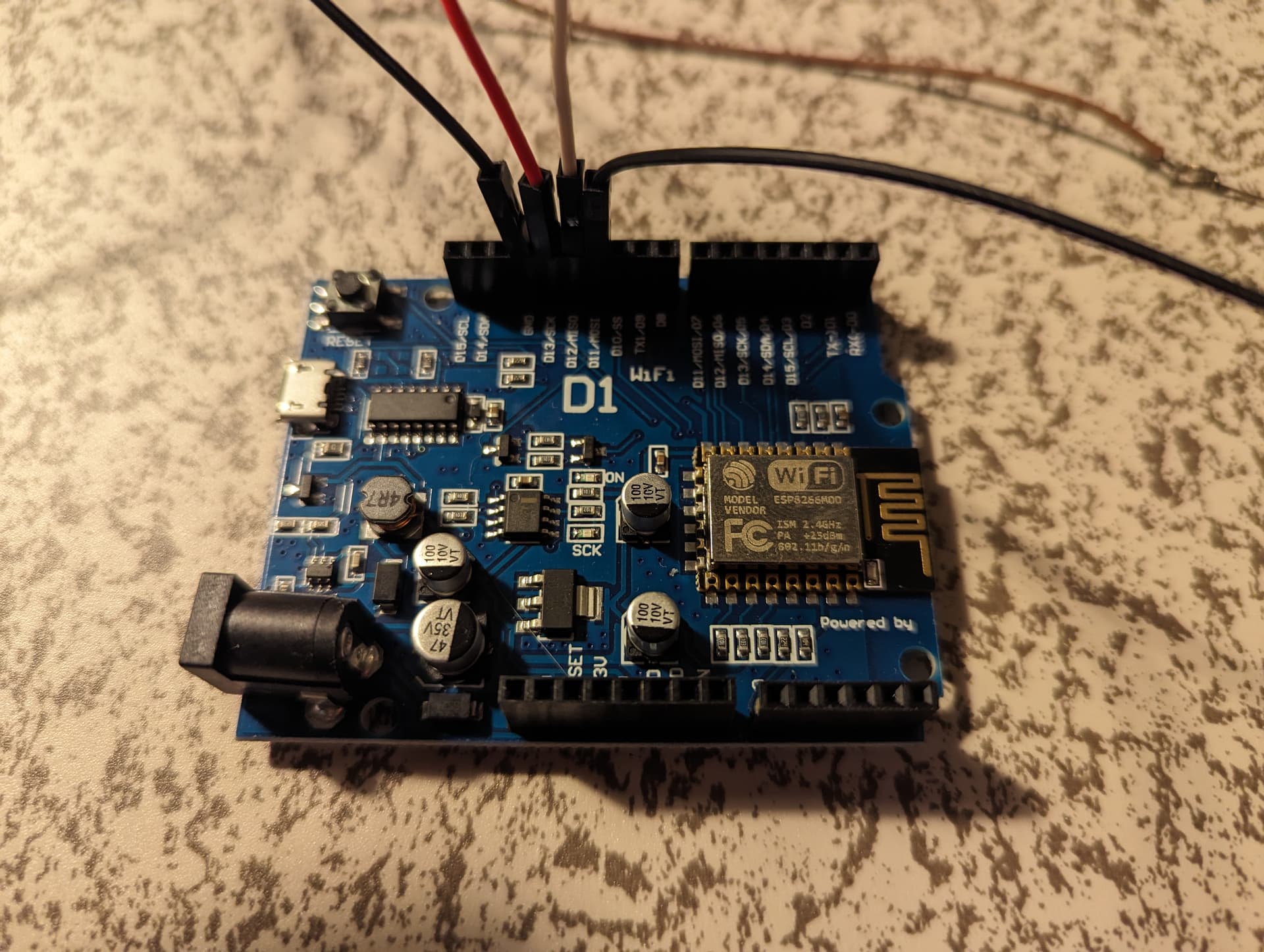
To keep things short, i've got a project that I'm working on with the board below. It is a Wemos ESP8266 D1 ESP-12F. I want to push a button, move a servo, LED comes on, servo moves back to origin, LED shuts off until next button press. I've done all the coding beforehand and with the help of an unbelievably helpful person on here i was able to work out a code that seems to work perfectly here. It was for a different board than the person i was getting it from ended up having but i assumed (perhaps wrongly) that they were similar enough that it would still work.
However when I hooked everything up (shown below) i can't get anything working at all. I tried every single component individually (through running super simple programs) and the only thing i could get to work was the button to turn on the internal LED on the board (i already ran sample sketches like blink just to be sure i was communicating with the board alright).
I'm assuming i'm doing something incredibly stupid but i'm not sure what it is because... well stupid I have a feeling maybe it's power? i thought the 5 volts from the usb would be enough to run the servo (according to its spec its 3-6v) and the LED (according to spec it just needs a 100ohm resistor) but I could be wrong on that.
If there's anyone out there that can tell if i'm doing something glaringly wrong please let me know. I'd love to figure this thing out!
Ah yes. The resistor is added based on the 20mA forward current of the LED which might not be correct...
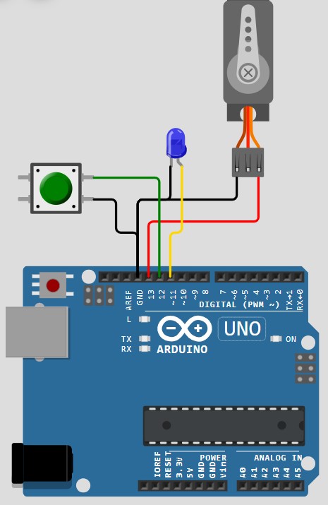
Added a little schematic to the OP. Hopefully that's clear. It's using a different board but the actual thing is currently set up the same exact way. All the grounds are tied together so those overlap but everything else shouldn't tie into anything else. If there's anything else i missed don't hesitate to let me know!
I don't know why but i thought the pins supplied enough voltage for the servo . Let me hook that empty contact to 5v and tinker with it to see if i can get it to work! I'll report back and see if i make any progress. but i think actually having power to the servo is the right track lol!
okay! After tinkering around with this for a bit i made some big progress.
I was able to get all components to work although the servo for whatever reason doesn't seem to be going through the full range (0-90 degrees, or 0-180 degrees or whatever the test program says) but i can work with that i think. it moves enough for me to be able to do what i'm trying to do but it's just odd that it's it's only covering like a quarter of the range the program is asking for. I tried all of the contacts and several different servos so i must be screwing something else up somewhere.
The LED i finally got working after trying a ton of different contacts. Some worked partially. some not at all. some lit the LED but not very bright, some lit the LED well but not when i wanted to (some lit it ONLY when the reset button was pressed??), and then i finally found one that seemed to do exactly what i was looking for.
Now i just got to try and put everything together and get all the components working together per the program but i'm confident i can get it working now that i got each component working individually