Successfully established connection between Leonardo (as Master) and Due (as Slave) with example code provided with libraries. BAS70 schottky diode is working perfectly well!
But somekind, I can not establish connection between Due (as Master) and Leonardo (as Slave). I'll try to research this problem soon.
Updated SimpleModbusMaster to V10. It now supports function 1, 2 and 15 with broadcasting also on 15. I have also altered the modbus_configure() method to allow the selection of different Serial instances (hardware serial ports).
I must say I have helped allot of users with the hardware side of the modbus protocol so here is a list of pre-flight checks:
120ohm termination resistors on either end of the bus line.
680ohm pull up and pull down resistors on bus line. Usually half way on the bus line depending on your layout.
Using a MAX487 which has a quarter unit load (48k vs standard 12k) the pull up and down resistor combination can theoretically drive 48 nodes.
Any voltage between -200mV and 200mV is not defined.
10k pull up resistor from the Rx line (MAX487 driver pin DI) to Vcc.
Make sure the slave supports the correct function.
Make sure about the correct address.
Both master and slave driver ic's must run on the same voltage usually 5V.
If the slave is not responding initially try increasing the timeout and polling values. You can also increase the retry count to help in debugging initially.
Writing (Function 16) usually takes longer than reading.
Use 2x twisted pair cable with shield on long distance communication where possible. The one pair you use for communication and the other either for 0V
or 0V and Vcc supply.
Contrary to popular believe RS485 is a 3 wire topology. You need a common reference (0V).
Connect a 100ohm 0.5W resistor in series between each node’s 0V and the bus line 0V to avoid excessive unbalanced current draw.
The only bad questions are no questions and then... frustration and smoke
Great update, but library does not compile successfully on IDE 1.5.2 (hope arduino team make an update on that soon!). The problem is again parity and now the hardwareserial.h added too.
And I'm still trying to figure out why communication is only working when Leonardo is master and Due is slave and not in the opposite way (Due as master and Leonardo as slave). I have checked all of your points from first to double nine (the very last one makes sense) I have checked all points except 2nd (only about MAX487 part -> way too expensive). I do not know what can cause this problem. I'm still on example code provided with libraries and will be using them till I find a solution for problem.
So what is the problem: Hardware seems ok (or maybe not, again!), since everything works fine when Leo as master and Due as slave. But when Due is master and send a message to Leonardo as slave, Leonardo does not respond to it. Leonardo does get the message (at least phisicaly), but TX on Leonardo just stays on 5V all the time. So master (due) continue sending messages to the slave, till retry_count counts to deifined nr.
Well this was genius! Exactly the solution I needed. I added a delay function of 3ms immediately after Serial.flush command in master library and now it works like a charm. I'm still not fully satisfied with this solution (delay command) so I will research this problem a bit more.
JuanB, I don't know how to thank you for all your help.
I'm having a modbus enabled meter which has kWh value in register 286. I have a python code to read the register the meter and i know the packet formatting also.
Can you please guide me how to read the register from this meter using arduino.
I have arduino Leonardo.
I tried simple modbus library with RS-485 chip from Maxim MAX485.
Follow the connection on the simpleModbus site. Use V10. Make sure you use a 10k pull up indicated on the drawing. What type of meter is it? I will help you with the code..
I'm using different meters.
The one i'm reading is Fineco Meters from china. they provide only kWh which is register 286 and no. of words to read is 2
I've ElMeasure meter also LG119. Address map : http://www.elmeasure.com/downloads/mod_lgplus.pdf
In elmeasure it says register 40159 but from my python code im reading address as 158 to get Wh reading instead of 40158 and no. of words to read is 2
On the Leo you can only use the Serial1 object. Although you have done this you cannot access the Serial1 object methods as this will conflict with the library. The information should be stored in the array you initialized the packet to, in this case readRegs[4]. This array contains the unsigned int values read from the slave. Since modbus only specifies unit16 values you will have to read 2 registers per float value. You will need to shift the two consecutive unsigned integers together to form the float32 value. You can then use Serial (USB) to transmit the two registers to the PC.
So the readRegs[4] contains the 4 words read from the slave.
readRegs[0] 1st word
readRegs[1] 2nd word
readRegs[2] 3rd word
readRegs[3] 4th word
Actually i want to read the registers and store the data on SD Card.
Arduino will read the data periodically and update the file by over writing the entries in the file.
The file will act as a sort of database.
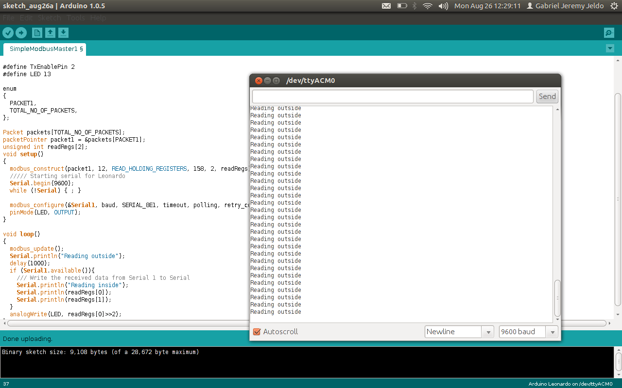
As of now just for debugging i am printing the output to Serial1.
The third attachment still uses Serail1.available() and the other one uses Serial1.read(). This wont work.
Use Serial.println(readRegs[]) or something similar like you already did to transmit the received values from Serial1 (the modbus connection). Again you cannot use Serial1.available() since it will most of the time be empty depending when you read it. The library reads the received information and stores it in the assigned register array, in this case readRegs[]. This is the only way of interfacing with the information received.
If you want to know if the request packet is successful than access the packets following information counters like this:
packet1->requests;
packet1->successful_requests;
packet1->failed_requests;
packet1->exception_errors;
Also try not to use delay() with values larger than 100ms. It will affect the polling and timeout values.
If you want to periodically send the received information from readRegs[] to Serial (USB) than rather use millis() in a timely manner or check if the value linked to the regdRegs[] index has changed.
void loop()
{
  modbus_update();
  //if (Serial1.available()){
    /// Write the received data from Serial 1 to Serial
    //Serial.println(Serial1.read());
    //Serial.println(readRegs[]);
    Serial.println(packet1->requests);
    Serial.println(packet1->successful_requests);
    Serial.println(packet1->failed_requests);
    Serial.println(packet1->exception_errors);
    //Serial.println(readRegs[1]);
  //}
  analogWrite(LED, readRegs[0]>>2);
}
but i'm getting
50
0
50
0
that is requests made 50 but all failed requests.
Even the comm. light on the meter is not blinking.