Help with using ls148 priority encoder midi controller

Im still very much a noob, i'm learning but I still have huge holes in my knowledge.

a link to the datasheet of the priority encoder http://www.ti.com/lit/ds/symlink/sn74ls148.pdf

I have 3 of these chained together and thus have 5 outputs from the encoders:
A0, A1, A2, GS of the second ls148 and GS of the third ls148
I have switches to ground on all the inputs of the encoders.

I am trying to build a midi controller that uses one single button (on pin 8 in my code) to trigger midi notes with the note number being determined by the output of the encoders. the switches on the encoder inputs should determine the note number.

EDIT -- Ultimately I would like to know how to make each encoder input (1-23) both select the midi note number AND trigger the note on /note off messages. Also a button on pin 8 should retrigger (apply note on) the last note number sent.

Here is the code

//https://github.com/tttapa/MIDI_controller

#include <MIDI_Controller.h>

HardwareSerialMIDI_Interface serialmidi = {Serial, MIDI_BAUD};


const uint8_t velocity = 0b1111111; // Maximum velocity (0b1111111 = 0x7F = 127)

int val;
int sixpin = 6; //  gs pin of third 74148
int fivepin = 5; //  gs pin of second 74148
int fourpin = 4; // A2 pin 
int threepin = 3; // A1 pin 
int twopin = 2; // A0 pin 


// Create a new instance of the class 'Digital', called 'button', on pin 8, that sends MIDI messages with note 'val' on channel 1, with velocity 127
Digital button(8, val, 1, velocity);

void setup() //Setup //
{
 pinMode(sixpin, INPUT); 
 pinMode(fivepin, INPUT);
 pinMode(fourpin, INPUT);
 pinMode(threepin, INPUT);
 pinMode(twopin, INPUT);
}

void loop()
{

  if (digitalRead(fourpin) == HIGH && digitalRead(threepin)== HIGH && digitalRead(twopin)== HIGH)
   {val = 28;} 
 else if (digitalRead(fourpin) == HIGH && digitalRead(threepin)== HIGH && digitalRead(twopin)== LOW)
   {val = 29;}
 else if (digitalRead(fourpin) == HIGH && digitalRead(threepin)== LOW && digitalRead(twopin)== HIGH)
   {val = 30;} 
 else if (digitalRead(fourpin) == HIGH && digitalRead(threepin)== LOW && digitalRead(twopin)== LOW)
   {val = 31;} 
 else if (digitalRead(fourpin) == LOW && digitalRead(threepin)== HIGH && digitalRead(twopin)== HIGH)
   {val = 32;} 
 else if (digitalRead(fourpin) == LOW && digitalRead(threepin)== HIGH && digitalRead(twopin)== LOW)
   {val = 33;} 
 else if (digitalRead(fourpin) == LOW && digitalRead(threepin)== LOW && digitalRead(twopin)== HIGH)
   {val = 34;}
 else if (digitalRead(fourpin) == LOW && digitalRead(threepin)== LOW && digitalRead(twopin)== LOW)
   {val = 35;}   
  if (digitalRead(fivepin) == LOW)
   {val = val + 8;}
  if (digitalRead(sixpin) == LOW)
   {val = val + 16;}


MIDI_Controller.refresh();

                          
}

In this line - Digital button(8, val, 1, velocity); - I can see that 'val' is 0 when creating the button instance and it does not see the changes to 'val' that happen in the loop. How can I make the changing values of 'val' apply to the Digital button?

Thanks
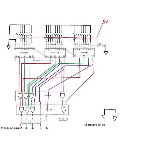
Can you post a schematic please, and while your at it modify that first post so the code is posted correctly as you read in the how to use this forum sticky sticky post, that you read before you posted anything. Didn’t you?

Look at the application example for chaining two 74148 and extend it for three chips. Extend your circuit as required and adjust your code accordingly.

Thanks for the reply Grumpy_Mike, I have amended the post and added a rather crude schematic.

I should note that if I serial print 'val' at the end of the loop, I do get the expected results in the serial monitor when grounding each encoder input. I just need to apply the value of 'val' to the note number of the midi note on / note off messages.

Cheers

I think that class Digital creates static buttons, whose properties can not normally be changed later.

Why don't you simply add the binary weights of the input pins? A0 has weight 2^0=1, A1 has weight 2^1=2 until GS2 has weight 2^4=16. Then add whatever note offset you want to apply.

thanks for you reply DrDiettrich

Being a newb I dont quite understand your suggestion. The midi library takes care of checking to see if the button is still pressed so as not to send a note off message until the button is depressed.

Are you able to provide an example? As seen in the code, I'd like input 1 to output midi note 28 (E1), input 2 to midi not 29 (F1) and so on

as mentioned I'd like the button connected to pin 8 to trigger the note on / note off messages.

Ultimately I would like to know how to make each encoder input (1-23) both select the midi note number AND trigger the note on /note off messages. Also a button on pin 8 should retrigger (apply note off/note on) the last note number sent.

Thanks

Ok you should really have posted those images as per instructions not on an external site.
You are using a 74LS device and are switching the input to 5V with a pull down resistor. That way of doing things doesn’t work unless the pull downs are very low, like 330R. You should have a pull up to 5V of 4K7 and switch the inputs to ground. Each chip needs a 0.1uF ceramic capacitor across its power and ground pins.

Edit - sorry you are using pull up resistors, it was the way you drew the schematic that had me confused.

Being a newb I dont quite understand your suggestion.

What he is saying is throw away all that circuitry and just connect the switches direct to the Arduino inputs. That means you switch say 5 inputs ( giving you 32 combinations of up and down) and in a binary pattern and convert that into a decimal number by software.

I also think that using that digital library is hampering things as you should not need it in any way. I for one have no idea what it is doing.

Sending the note on message when you read pin 8 as being pressed and send the note off message when it is released. You need to look at the state change example in the IDE.

Forget the MIDI bit until you can get a proper reading from your hardware, build up things one step at a time.

I think your circuit is a bit suspect. You do know that the way those encoders work is that they will only take notice of the highest number input that is connected low, ignoring all the other switches. Is that what you want?

Thanks Mike, I appreciate the help

I am aware the encoder takes the highest input, It is needed. I am not using the priority flags currently.

The concept is a one stringed midi bass guitar using the frets and strings as contact switches. The encoder inputs are wired to the frets of the guitar and the bass string is grounded.

I have the setup working, tested using the following code. It outputs the right values in the serial monitor

int val;
int sixpin = 6; //  gs pin of third 74148
int fivepin = 5; //  gs pin of second 74148
int fourpin = 4; // A2 pin 
int threepin = 3; // A1 pin 
int twopin = 2; // A0 pin 


void setup() //Setup //
{
 pinMode(sixpin, INPUT);
 pinMode(fivepin, INPUT);
 pinMode(fourpin, INPUT);
 pinMode(threepin, INPUT);
 pinMode(twopin, INPUT);
}

void loop()
{

  if (digitalRead(fourpin) == HIGH && digitalRead(threepin)== HIGH && digitalRead(twopin)== HIGH)
   {val = 28;}
 else if (digitalRead(fourpin) == HIGH && digitalRead(threepin)== HIGH && digitalRead(twopin)== LOW)
   {val = 29;}
 else if (digitalRead(fourpin) == HIGH && digitalRead(threepin)== LOW && digitalRead(twopin)== HIGH)
   {val = 30;}
 else if (digitalRead(fourpin) == HIGH && digitalRead(threepin)== LOW && digitalRead(twopin)== LOW)
   {val = 31;}
 else if (digitalRead(fourpin) == LOW && digitalRead(threepin)== HIGH && digitalRead(twopin)== HIGH)
   {val = 32;}
 else if (digitalRead(fourpin) == LOW && digitalRead(threepin)== HIGH && digitalRead(twopin)== LOW)
   {val = 33;}
 else if (digitalRead(fourpin) == LOW && digitalRead(threepin)== LOW && digitalRead(twopin)== HIGH)
   {val = 34;}
 else if (digitalRead(fourpin) == LOW && digitalRead(threepin)== LOW && digitalRead(twopin)== LOW)
   {val = 35;}  
  if (digitalRead(fivepin) == LOW)
   {val = val + 8;}
  if (digitalRead(sixpin) == LOW)
   {val = val + 16;}


Serial.println(val);

                          
}

Ultimately I would like to know how to make each encoder input (1-23) both select the midi note number AND trigger the note on /note off messages. A button on pin 8 should retrigger (send note off/ note on) the last note number sent. (this is for right hand triggering)

Your circuit is okay. You can remove the Gnd on input 0 of the first 74148 and use its EO instead of the switch on pin 8. Or on another pin, if you want further functionality on the pin 8 switch. For the pin weights learn a bit more about the binary number composition from bits.

I don't know how your library can send a variable midi note, find out yourself or give a link to the library description.

DrDiettrich:
I think that class Digital creates static buttons, whose properties can not normally be changed later.

Exactly, it stores a copy of the value, not a reference. If you change the value of your "val" variable, the "Digital" class doesn't see that change, it still sees the original value from when it was initialized.

The "Digital" class is designed to be able to read buttons connected to Arduino pins, multiplexers and other IO expanders that implement the library's ExtendedInputOutput interface.
Priority encoders aren't supported out of the box, because they aren't commonly used to read buttons.

The MIDI Controller library has been obsoleted by the Control Surface library, please consider upgrading to Control Surface.

DrDiettrich:
I don't know how your library can send a variable midi note, find out yourself or give a link to the library description.

Using the latest version of Control Surface, you can manually send MIDI like this:

[color=#5e6d03]#include[/color] [color=#434f54]<[/color][b][color=#d35400]Control_Surface[/color][/b][color=#434f54].[/color][color=#000000]h[/color][color=#434f54]>[/color]

[b][color=#d35400]HardwareSerialMIDI_Interface[/color][/b] [color=#000000]serialmidi[/color] [color=#434f54]=[/color] [color=#000000]{[/color][b][color=#d35400]Serial[/color][/b][color=#434f54],[/color] [color=#00979c]MIDI_BAUD[/color][color=#000000]}[/color][color=#000000];[/color]

[color=#00979c]void[/color] [color=#5e6d03]setup[/color][color=#000000]([/color][color=#000000])[/color] [color=#000000]{[/color]
  [b][color=#d35400]Control_Surface[/color][/b][color=#434f54].[/color][color=#d35400]begin[/color][color=#000000]([/color][color=#000000])[/color][color=#000000];[/color]
[color=#000000]}[/color]

[color=#5e6d03]using[/color] [color=#5e6d03]namespace[/color] [color=#000000]MIDI_Notes[/color][color=#000000];[/color]
[b][color=#d35400]MIDIAddress[/color][/b] [color=#000000]noteaddress[/color] [color=#434f54]=[/color] [color=#000000]note[/color][color=#000000]([/color][color=#000000]C[/color][color=#434f54],[/color] [color=#000000]4[/color][color=#000000])[/color][color=#000000];[/color]
[color=#00979c]uint8_t[/color] [color=#000000]velocity[/color] [color=#434f54]=[/color] [color=#000000]127[/color][color=#000000];[/color]

[color=#00979c]void[/color] [color=#5e6d03]loop[/color][color=#000000]([/color][color=#000000])[/color] [color=#000000]{[/color]
  [b][color=#d35400]Control_Surface[/color][/b][color=#434f54].[/color][color=#5e6d03]loop[/color][color=#000000]([/color][color=#000000])[/color][color=#000000];[/color]
  [b][color=#d35400]Control_Surface[/color][/b][color=#434f54].[/color][color=#d35400]sendNoteOn[/color][color=#000000]([/color][color=#000000]noteaddress[/color][color=#434f54],[/color] [color=#000000]velocity[/color][color=#000000])[/color][color=#000000];[/color]
[color=#000000]}[/color]

That being said, the idiomatic way to change the address of a MIDI element using the Control Surface library is to use banks.

For example:

#include <Control_Surface.h>

HardwareSerialMIDI_Interface serialmidi = {Serial, MIDI_BAUD};

const pin_t sixpin = 6; //  gs pin of third 74148
const pin_t fivepin = 5; //  gs pin of second 74148
const pin_t fourpin = 4; // A2 pin
const pin_t threepin = 3; // A1 pin
const pin_t twopin = 2; // A0 pin

// Create a bank to change the address of the note button
OutputBank bank;

// Create a note button with a base address of 0. The bank offset will be
// added to this address.
Bankable::NoteButton notebtn = {bank, 8, 0}; // {bank, button pin, base address}

void setup() {
  Control_Surface.begin();
  pinMode(sixpin, INPUT);
  pinMode(fivepin, INPUT);
  pinMode(fourpin, INPUT);
  pinMode(threepin, INPUT);
  pinMode(twopin, INPUT);
}

void loop() {
  uint8_t val = 0;
  if (digitalRead(fourpin) == HIGH && digitalRead(threepin) == HIGH && digitalRead(twopin) == HIGH) {
    val = 28;
  } else if (digitalRead(fourpin) == HIGH && digitalRead(threepin) == HIGH && digitalRead(twopin) == LOW) {
    val = 29;
  } else if (digitalRead(fourpin) == HIGH && digitalRead(threepin) == LOW && digitalRead(twopin) == HIGH) {
    val = 30;
  } else if (digitalRead(fourpin) == HIGH && digitalRead(threepin) == LOW && digitalRead(twopin) == LOW) {
    val = 31;
  } else if (digitalRead(fourpin) == LOW && digitalRead(threepin) == HIGH && digitalRead(twopin) == HIGH) {
    val = 32;
  } else if (digitalRead(fourpin) == LOW && digitalRead(threepin) == HIGH && digitalRead(twopin) == LOW) {
    val = 33;
  } else if (digitalRead(fourpin) == LOW && digitalRead(threepin) == LOW && digitalRead(twopin) == HIGH) {
    val = 34;
  } else if (digitalRead(fourpin) == LOW && digitalRead(threepin) == LOW && digitalRead(twopin) == LOW) {
    val = 35;
  }
  if (digitalRead(fivepin) == LOW) {
    val = val + 8;
  }
  if (digitalRead(sixpin) == LOW) {
    val = val + 16;
  }
  // select an offset of `val` to be added to the base addresses of the elements in the bank
  bank.select(val); 
  Control_Surface.loop();
}

The big advantage of using banks is that the address of the MIDI Note Off event will always match the address of the corresponding Note On event.

Pieter

The concept is a one stringed midi bass guitar using the frets and strings as contact switches. The encoder inputs are wired to the frets of the guitar and the bass string is grounded.

Thanks, that makes all the difference. It turns your problem into a real one instead of an abstract exercise. You can instantly see why you would want a priority encoder for this.

Well I would do it like this, this compiles but haven't tested it due to not having your hardware:-

// for a start lets give the pins meaningful names
// The input bits derviced from the 74148 are bit in what you want as a number
int val;
byte bit4 = 6; //  gs pin of third 74148
byte bit3 = 5; //  gs pin of second 74148
byte bit2 = 4; // A2 pin
byte bit1 = 3; // A1 pin
byte bit0 = 2; // A0 pin

void setup() //Setup //
{
 pinMode(bit0, INPUT);
 pinMode(bit1, INPUT);
 pinMode(bit2, INPUT);
 pinMode(bit3, INPUT);
 pinMode(bit4, INPUT);
}

void loop() {
  val = readInput();
  Serial.println(val);
  delay(800) ; // to stop output going too fast                        
}

byte readInput() { // written in not quite the best way but more so it is understandable
  byte number, in0, in1, in2, in3, in4;
  in0 = digitalRead(bit0);
  in1 = digitalRead(bit1);
  in2 = digitalRead(bit2);
  in3 = digitalRead(bit3);
  in4 = digitalRead(bit4);
  // now combine these five bits into one number
  // | is the inclusive OR operator and << is shift left
  number = in0 | (in1 << 1) | (in2 << 2) | (in3 << 3) | (in4 << 4);
  return number;      
}

byte altReadInput() { // probably how I would do it
  return(digitalRead(bit0) | (digitalRead(bit1) << 1) | (digitalRead(bit2) << 2) | (digitalRead(bit3) << 3) | (digitalRead(bit4) << 4) );      
}

combine all the bits into a single number. Get this bit going first, the MIDI bit is a piece of cake and you have no need to use any libraries at all.

I did make a two stringed bass using bungy chord, and opto slot switches to detect its vibration. Then sent MIDI out depending on what button was last pressed. I work with Drake Music North, a group of volunteers who make and adapt instruments for disabled people.

I called this a Bat Bass, because the piece of oak floor board looked like a cricket bat. ( double pun ).

Thanks again for your help Mike, your work looks amazing. Fulfilling no doubt also :slight_smile:

I tried the code (both versions of "readInput") and can't seem to get a result in the serial monitor at all.
I feel as though I missing something simple...

Also, I couldn't find mention of 0.1uF ceramic capacitor across power and ground. Is this assumed knowledge?

Cheers
Leigh

bryanfury:
I tried the code you provided but am getting incorrect values. Some inputs will return a certain value and after a few or sometimes many button presses will then output another value.

I just copied your code, it was just a demonstration of how to use banks. If you get incorrect results, then it's probably a mistake in either the wiring or the logic in the if-statements to determine the value of "val".

bryanfury:
The other issue is I require these inputs to trigger the midi notes without pressing the button. The button is used to retrigger the last input value. I intend to have the open string note of the guitar to be triggered with the button only.

In that case, it's probably easier to just call Control_Surface.sendNoteOn(...) manually, without using the Digital/NoteButton classes.

Thanks Pieter

I need to troubleshoot some more. I appreciate the help

Success, I had a wire go loose on the veroboard wiring...

Pieter, your code works fine, thank you. I don't know how to implement the "Control_Surface.sendNoteOn(...)" suggestion, can you please elaborate or provide a small example?

Thanks again

Also, I couldn't find mention of 0.1uF ceramic capacitor across power and ground. Is this assumed knowledge?

Yes.
I wrote about it here
http://www.thebox.myzen.co.uk/Tutorial/De-coupling.html

bryanfury:
Pieter, your code works fine, thank you. I don't know how to implement the "Control_Surface.sendNoteOn(...)" suggestion, can you please elaborate or provide a small example?

In the code I posted earlier, the "NoteButton" class sends MIDI messages when the button is pressed or released. You can see a simplified version of how it works here. If the code is overwhelming, you can just focus on the "MyNoteButton::update()" function: when the button is pressed, it sends a Note On message, when it's released, it sends a Note Off message.

If you want MIDI messages to be sent when the values of the priority encoder change, you'll have to write your own logic and code to send these messages.

#include <Control_Surface.h>

HardwareSerialMIDI_Interface serialmidi = {Serial, MIDI_BAUD};

const pin_t sixpin = 6; //  gs pin of third 74148
const pin_t fivepin = 5; //  gs pin of second 74148
const pin_t fourpin = 4; // A2 pin
const pin_t threepin = 3; // A1 pin
const pin_t twopin = 2; // A0 pin

// Create a bank to change the address of the note button
OutputBank bank;

// Create a note button with a base address of 0. The bank offset will be
// added to this address.
Bankable::NoteButton notebtn = {bank, 8, 0}; // {bank, button pin, base address}

void setup() {
  Control_Surface.begin();
  pinMode(sixpin, INPUT);
  pinMode(fivepin, INPUT);
  pinMode(fourpin, INPUT);
  pinMode(threepin, INPUT);
  pinMode(twopin, INPUT);
}

void loop() {
  uint8_t val = 0;
  if (digitalRead(fourpin) == HIGH && digitalRead(threepin) == HIGH && digitalRead(twopin) == HIGH) {
    val = 28;
  } else if (digitalRead(fourpin) == HIGH && digitalRead(threepin) == HIGH && digitalRead(twopin) == LOW) {
    val = 29;
  } else if (digitalRead(fourpin) == HIGH && digitalRead(threepin) == LOW && digitalRead(twopin) == HIGH) {
    val = 30;
  } else if (digitalRead(fourpin) == HIGH && digitalRead(threepin) == LOW && digitalRead(twopin) == LOW) {
    val = 31;
  } else if (digitalRead(fourpin) == LOW && digitalRead(threepin) == HIGH && digitalRead(twopin) == HIGH) {
    val = 32;
  } else if (digitalRead(fourpin) == LOW && digitalRead(threepin) == HIGH && digitalRead(twopin) == LOW) {
    val = 33;
  } else if (digitalRead(fourpin) == LOW && digitalRead(threepin) == LOW && digitalRead(twopin) == HIGH) {
    val = 34;
  } else if (digitalRead(fourpin) == LOW && digitalRead(threepin) == LOW && digitalRead(twopin) == LOW) {
    val = 35;
  }
  if (digitalRead(fivepin) == LOW) {
    val = val + 8;
  }
  if (digitalRead(sixpin) == LOW) {
    val = val + 16;
  }
  // select an offset of `val` to be added to the base addresses of the elements in the bank
  bank.select(val);
  Control_Surface.loop();
  delay (2);
}

I have attached the output of the "priority flag" to pin 8, thus sending out midi note on messages when an encoder input is grounded and note off when the "button" is let go of. The only problem remaining is that if I ground an input then move to another input without lifting off/letting go of the "button", no midi messages are sent.

Is there a way to implementing this with the current code?

I am also exploring manually sending the messages as was suggested but am struggling with the logic to account for playing the notes but also checking if the new note is the same as previous note (and to not retrigger it)

bryanfury:
I have attached the output of the "priority flag" to pin 8, thus sending out midi note on messages when an encoder input is grounded and note off when the "button" is let go of. The only problem remaining is that if I ground an input then move to another input without lifting off/letting go of the "button", no midi messages are sent.

Is there a way to implementing this with the current code?

I don't know enough about the priority encoder you're using to answer that question.

Even if it's possible, writing your own logic in software will be much more flexible.