It is at the side of the diode - I don't think you can see it in the diagram since the diode covers it.
Are the batteries good?
Is there any possibility that the batteries still can't provide enough current because of the resistance in the transistor path?
When isolated without connection to pin 2 it does click.
I think so, since it can power the relay by itself.
Disconnect the wire from pin 2 and temporarily connect it to Uno 5V.
Does the relay click?
No, it doesn't seem to.
Also I've confirmed that toggling pin 2 works as I have used it with an LED
Ok one last test.
If you have a 330Ω or 470Ω resistor, replace the 1K resistor with it.
If it still does not work, then either you have a bad breadboard or the transistor is bad
the closest I have is a 560, would that be fine?
actually never mind, I'll just do two 220 ohm resistors in series
560 or two 220 in series is fine
It doesn't work either. I'm just confused because the relay works when I isolate it, and the transistor works when I connect an LED to it, but they don't work when connected
Do you have another transistor you can try?
I have replaced the transistor but it still does not work.
I'll add a picture of my wiring in case I've missed something.
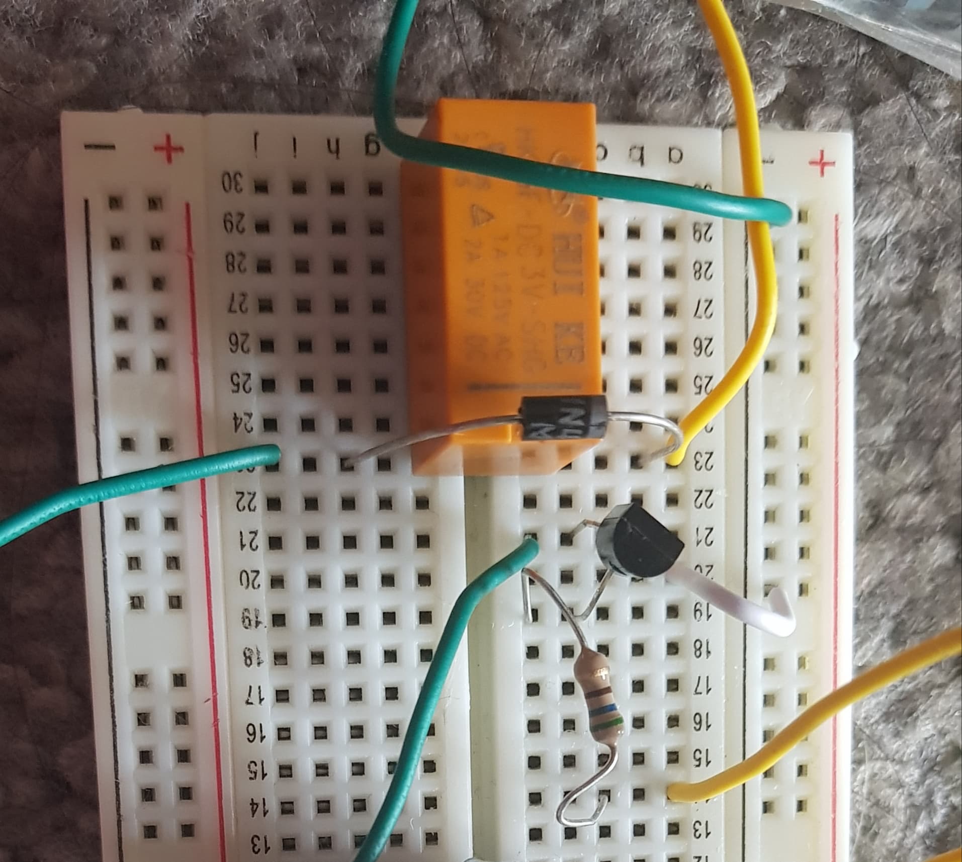
The yellow wire is connected to the positive terminal of the battery and the green to the negative terminal.
The large green wire which is cut out from the screen is the same wire.
Looks like the transistoe may be backwards.
Can't tell if it's corrent since there are two yellow and three green
I didn't think it was because it can connect to pin 2 to toggle an LED without a problem.
The top yellow wire is the positive terminal, top green is negative terminal.
The bottom green wire connects from the collector to the diode and the bottom yellow wire is from pin 2 of the Arduino
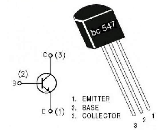
Just curious since it seems that I have switched the emitter and collector around - how is it possible that this has worked with the LED?
You would have to show me exactly how you had it connected when you made that test.
I connected it the wrong way with the collector to GND and the emitter to the resistor and LED and it worked, which is why I thought that it was correct.
I have switched it around now and it also works with an LED, so that's most probably my mistake.