I think what I'm trying to do is create a HID joystick with a few rotaries.
The idea is to have a few rotaries to control Radar Horizontal/Vertical/Range on various aircraft in DCS World, since the HOTAS Warthog has none of these. If I can make it work I think I'd like to 3d print something to put this all in to attach to the back of the hotas by attaching it where a couple screws are located. But anyway, for me the hard part first:
I've never done anything like this whatsoever, but it seems the Arduino Uno can behave as a HID Joystick, from reading. Is this correct?
And finally, I see some tutorials for joysticks with a couple potentiometer and a couples buttons, but not so much for rotaries. The rotary examples are incomplete, and being an utter newb I'm getting lost quick. Maybe just because I don't even know what I'm searching for. Does anyone know of a detailed tutorial or example using rotaries in this manner?
They seem to assume some knowledge about doing this kind of stuff and I see little about rotary encoder examples. Again most are buttons and or potentiometers.
Hi,
HID Human Interface Device, ie the joystick to ardunio to USB.
The joysticks usually are potentiometers, apart from cheap over priced games joysticks which can be just 4 tactile switches under a joystick lever.
Yes the arduino can input the joystick analog values.
Now in plain English, what do you want to interface it with.
What do you want to connect the arduino to?
The arduino will have a digital value for each of the joystick positions.
Remember we are not all gamers, so forget using all the pseudonyms and read back what you have written before posting.
MrGingerwig:
Now as for doing the rotaries, as you are using them for radar scale etc I would try getting your Arduino/Promicro to read them as analogue.
How can you read the digital output of a rotary encoder "as analogue" ?
I emphasize the "I would try" as I figured, as @xaoslaad was talking about using them on a joystick for controlling radar he was talking more about a rotary wheel that you find on some joysticks to control throttle or trim axis. These are read as an analog axis as opposed to digital positions of a switch.
If like you said he is going to use rotary switches that have a set number of positions then yes, he won't be able to use analogRead().
How the game allows you to change these settings is also important as I know games like Elite:Dangerous allow for an axis to change "radar zoom" in which case you wouldn't be able to make it recognise a digital input such as a rotary switch OR it allows two keybindings, one for increase zoom and one for decrease. Again, I'm not sure how the game would deal with a rotary switch as it only wants two separate inputs.
All in all I think the OP would be best with some kind of rotary wheel that reads as analog, as opposed to a rotary switch....all in my opinion of course.
I think you can get potentiometer thumbwheels on Ebay for peanuts and that would make the coding much easier.
Robin2:
I was just going by the link he included in his Original Post.
...R
My apologies, I had totally missed that link.
So it works by measuring the difference between two channels and the output will depend on whether it is going clockwise or counter-clockwise.
//From bildr article: http://bildr.org/2012/08/rotary-encoder-arduino/

//these pins can not be changed 2/3 are special pins
int encoderPin1 = 2;
int encoderPin2 = 3;
int encoderSwitchPin = 4; //push button switch

volatile int lastEncoded = 0;
volatile long encoderValue = 0;

long lastencoderValue = 0;

int lastMSB = 0;
int lastLSB = 0;

boolean buttonPushed = false;

void setup() {
  Serial.begin (9600);

  pinMode(encoderPin1, INPUT);
  pinMode(encoderPin2, INPUT);

  pinMode(encoderSwitchPin, INPUT);


  digitalWrite(encoderPin1, HIGH); //turn pullup resistor on
  digitalWrite(encoderPin2, HIGH); //turn pullup resistor on

  digitalWrite(encoderSwitchPin, HIGH); //turn pullup resistor on


  //call updateEncoder() when any high/low changed seen
  //on interrupt 0 (pin 2), or interrupt 1 (pin 3)
  attachInterrupt(0, updateEncoder, CHANGE);
  attachInterrupt(1, updateEncoder, CHANGE);

}

void loop(){
  //Do stuff here
  if(digitalRead(encoderSwitchPin)){
    //button is not being pushed
  }else{
    //button is being pushed
    Serial.println("button pushed");
    buttonPushed = true;
  }

  Serial.println(encoderValue);
  delay(1000); //just here to slow down the output, and show it will work  even during a delay
}


void updateEncoder(){
  int MSB = digitalRead(encoderPin1); //MSB = most significant bit
  int LSB = digitalRead(encoderPin2); //LSB = least significant bit

  int encoded = (MSB << 1) |LSB; //converting the 2 pin value to single number
  int sum  = (lastEncoded << 2) | encoded; //adding it to the previous encoded value

  if(sum == 0b1101 || sum == 0b0100 || sum == 0b0010 || sum == 0b1011) encoderValue ++;
  if(sum == 0b1110 || sum == 0b0111 || sum == 0b0001 || sum == 0b1000) encoderValue --;

  lastEncoded = encoded; //store this value for next time
}
I wrote it out in Arduino and it compiles OK but I have no rotary switch to try it.
//these pins can not be changed 2/3 are special pins
int encoderPin1 = 2;
int encoderPin2 = 3;
int encoderSwitchPin = 4; //push button switch
volatile int lastEncoded = 0;
volatile long encoderValue = 0;
long lastencoderValue = 0;
int lastMSB = 0;
int lastLSB = 0;
boolean buttonPushed = false;
void setup() {
// put your setup code here, to run once:
Serial.begin (9600);
pinMode(encoderPin1, INPUT);
pinMode(encoderPin2, INPUT);
pinMode(encoderSwitchPin, INPUT);
digitalWrite(encoderPin1, HIGH); //turn pullup resistor on
digitalWrite(encoderPin2, HIGH); //turn pullup resistor on
digitalWrite(encoderSwitchPin, HIGH); //turn pullup resistor on
//call updateEncoder() when any high/low changed seen
//on interrupt 0 (pin 2), or interrupt 1 (pin 3)
attachInterrupt(0, updateEncoder, CHANGE);
attachInterrupt(1, updateEncoder, CHANGE);
Gamepad.begin();
}
void loop()
{
if (!digitalRead(encoderSwitchPin))
Gamepad.press(3);
else
Gamepad.release(3);
Serial.println(encoderValue);
delay(1000); //just here to slow down the output, and show it will work even during a delay
}
void updateEncoder()
{
int MSB = digitalRead(encoderPin1); //MSB = most significant bit
int LSB = digitalRead(encoderPin2); //LSB = least significant bit
int encoded = (MSB << 1) |LSB; //converting the 2 pin value to single number
int sum = (lastEncoded << 2) | encoded; //adding it to the previous encoded value
if(sum == 0b1101 || sum == 0b0100 || sum == 0b0010 || sum == 0b1011) encoderValue ++;
if(sum == 0b1110 || sum == 0b0111 || sum == 0b0001 || sum == 0b1000) encoderValue --;
if(encoderValue < lastencoderValue)
   Gamepad.press(1);
   else
      Gamepad.release(1);      //counter-clockwise activates DX1

if(encoderValue > lastencoderValue)
   Gamepad.press(2);
   else
      Gamepad.release(2);      //clockwise turn activates DX2

encoderValue = 0; //reset encoderValue to zero
lastEncoded = encoded; //store this value for next time
}
If anyone is curious how I am trying to attempt this, I am doing it first with a Leonardo and breadboard and once I figure out how to do that I will use a Pro Micro and do some soldering work.
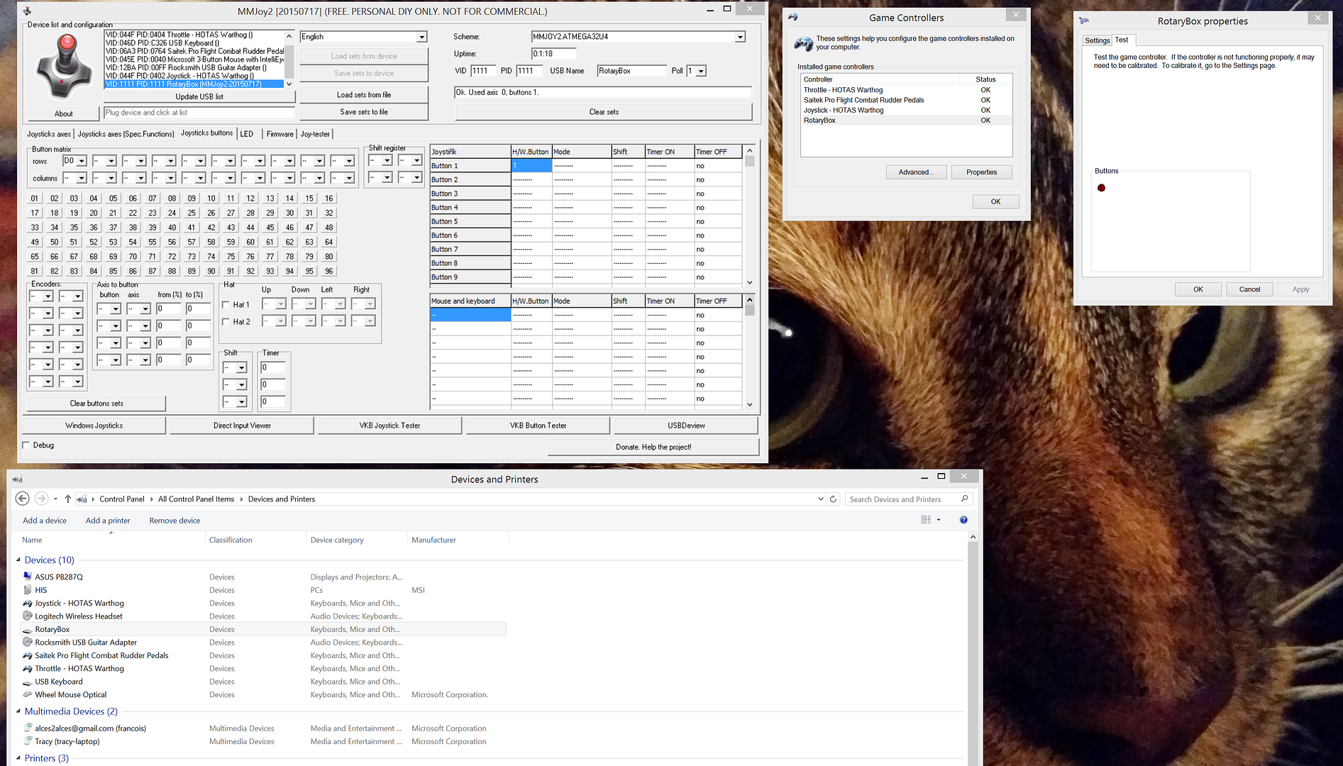
The software is MMJoy2 which allows you to flash a firmware that presents the device as a game controller. From here you can program buttons, encoders, axes, etc.
Here's a view of the software and a Leonardo configured to look like a game controller.
I just have it set up as a single button controller at the moment as the breadboard, wires, resistors, capacitors, etc. are in a second package I'll probably get tomorrow, so maybe over the weekend I can get it working as a prototype.
xaoslaad:
If anyone is curious how I am trying to attempt this, I am doing it first with a Leonardo and breadboard and once I figure out how to do that I will use a Pro Micro and do some soldering work.
The software is MMJoy2 which allows you to flash a firmware that presents the device as a game controller. From here you can program buttons, encoders, axes, etc.
Here's a view of the software and a Leonardo configured to look like a game controller.
I just have it set up as a single button controller at the moment as the breadboard, wires, resistors, capacitors, etc. are in a second package I'll probably get tomorrow, so maybe over the weekend I can get it working as a prototype.
I've got it more or less working with one rotary. Adding more should be no problem. I'm going to start doing some of the soldering so I can clean up once some additional parts get here.
This SimHQ post shows that I should have diodes in place, which I have not received yet. So for now it only work OK if I turn the knob at a steady and deliberate pace.
The software also lets you optionally configure a button to re-center the access.
Final build connected to the back of the throttle. Inside is just a Arduino Leonardo and a mini-breadboard. Can add more controls in the future if I choose.

