Hi, I am a new Arduino user, and can't find anything similar here. I want a variable voltage, high current amplifier to drive a large electromagnet. The coil is about 5 ohms (DC), but high impedance at 10 kHz, so I can't use a standard MOSFET with a high switching frequency. I need to send up to 7 amps though the coil, and the current will normally change from 0 to 7 amps over a few seconds, then back down again. Audio amplifiers won't allow such a low frequency. I suspect I need a standard power transistor with a good heat sink, but I was hoping to find a pre-built module ready to plug in. Any suggestions are appreciated!
Yes, the coil has high impedance at 10 kHz. I don't see what that has to do with your project, or why you think a MOSFET is not suitable, since that is what everyone else uses.
I need to send up to 7 amps though the coil
No problem whatsoever, as long as your 35 VDC (or higher) power supply can handle that.
You will need serious cooling, as the coil will be dissipating around 175W at full current.
“I want a variable voltage,“
An Arduino like the UNO cannot give a variable output voltage by itself.
What is the maximum frequency you will be sending to the magnet ?
Cannot imaging a 5 ohm 7 amp electromagnet will respond well to 10kHz.
How will you be managing with the inductive kickback voltages ?
What is this electromagnet ?
Do you think the massive motors that MOSFET drivers can power, are not inductive, don't have coils?
HI, Thanks for your quick reply. What I meant was that a PWM controller usually operates at 10kHz or higher, so the current would not get through the coil; too high impedance at that frequency. I thought that MOSFETS were only on-off switches, so modulating the output to control the average current would not work well. That is why I need a programmable power supply, essentially, a linear power transistor type. Am I wrong or confused?
Hi. The maximum frequency I need to send to the coil is only about 1 Hz, ramping up and down to zero, so there should be no inductive kickback. I wound the coil using 20 gauge wire, so its a home-made device.
Hi, I thought that most motors that are driven by MOSFETS have a small inductance. My coil is pretty big!
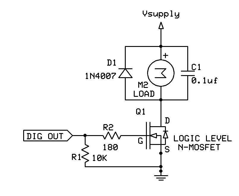
A MOSFET will work for this.
Make sure you use a Logic Level MOSFET for the Arduino voltage you are using.
Just one ON/OFF operation will generate enough kickback voltage to destroy things.
Use a kickback diode, 8 to 10 amp rating.
Hi Larry,
I don't want an ON/OFF controller, and I thought that is how MOSFETS work. I will slowly be ramping up the voltage from 0 to 15 V over one second, and then turning the voltage down to zero. This should minimize the back EMF from the inductance. I thought I needed an analog power transistor to give the intermediate voltages. This would generate a lot of heat in the transistor, so I need to heat sink that, too. I was hoping that some vendor already makes an analog voltage controller that can be programmed by the Arduino, and provide the high current I need.
Thanks,
Don
If you are using the Arduino, you can only turn things ON or OFF, no ramping.
I understand. I remember there were analog inputs, I forgot there were
no analog outputs. A DAC should be easy to implement, or the
programmable high-current module I am looking for would have a digital
input. The high-current driver is still what I need to find, or build.
You are obviously confused about and/or misunderstand how a PWM controller works. By varying the ON time, you are in effect varying the average DC voltage across the inductor.
This is not an AC circuit.
The high-current driver is still what I need to find, or build.
Use a simple logic level MOSFET, like everyone who understands this does quite successfully.
Hi,
It seems to me that a PWM controller would not work to drive a large
inductance. The effective time when the PWM is at 50%, for example, is
in the microsecond regime, and the inductance would act as a high
impedance, preventing any current flow. For a 100 kHz PWM, this is
similar to a 100 kHz sine wave, I thought. If the MOSFET is simply
turned on or off, the PWM frequency would have to be very low. I found
one that operates down to 200 Hz, which might work, but would generate a
lot of audio. A PWM that worked at 30 Hz would be good.
Don
No idea what this means since all transistors will happily work down to DC. There are MOSFETs driving motors much larger than your coil, so I really don't know what you think the issue is.
Default arduino PWM frequency is 500Hz, so at 50% duty cycle the coil will be on for 1ms. If you are concerned about the inductive effects of your coil at that frequency, you can change the frequency of arduino PWM. Google "change arduino pwm frequency" for suggestions.
Sorry, but I still get the feeling that you don't really understand how this works.
In the face of such grossly misinformed obstinance, I give up.
Good luck with your project!
Hi,
I hope I can explain a little better here. My coil is big, so the
inductance is a problem at high frequencies. I made some measurements
this morning so I could use real numbers. I put a 1.5 ohm resistor in
series with the 2.7 ohm coil so I could monitor the current through the
coil with an oscilloscope. Here is what I found.
At 500 Hz (the lowest Arduino PWM frequency), at 50% duty cycle, the
coil reactance increase from 2.7 ohm (at DC) to 3.6 ohm. This would
limit the current by a factor of 1.4. At this frequency, the sound
emitted by the coil is very loud.
At 5000 Hz, the sound is reduced due to my hearing, but also now the
reactance is up to 5 ohms. This limits the coil current by a factor of two.
I might wonder if this is a problem, because at 100% duty cycle, the
current is nearly constant, so the reactance drops back down to 2.7
ohms. At low duty cycle, the reactance increases even higher, but that
is what the low duty cycle is for. The end result is that the current is
not linear with duty cycle, so I can't set the control to 30% and expect
30% current. Since I will be using a feedback circuit anyway, maybe this
non-linearity is OK.
The alternative control circuit uses a simple power transistor, which
would be linear, but would require a heat sink. This is what I was
originally posting about, but I guess I'll try a PWM at 5 kHz and see if
it would work OK.
Thanks,
Don
... if it was bipolar. and symmetrical, with no DC offset. But the MOSFET PWM has two components superimposed - the PWM frequency, and DC. The PWM frequency can be attenuated by the coil (but that is just a good thing), but the DC component observes only the DC resistance of the coil.
In this situation, the coil is acting as a low pass filter, and that seems to be what you are looking for. Or at least,sufficient for what you need.
Hi,
Thanks for your earlier comments. Please see my detailed reply to
cedarlakesinstruments. I measured the reactance of the coil this morning
with a small resistor and an oscilloscope, and see that the effective
impedance is reduced by a factor of two at 5 kHz PWM base frequency. The
SMC controller from Polulu that I was using has a PWM frequency range
from 1.13kHz to 22.5 kHz. At the higher frequency, the current is
severely reduced. I can only try at 5kHz and work with the non-linear
PWM response function. Please look at that explanation, I hope it helps.
Don
That's interesting, but were you measuring AC or DC current?
Everything from blenders to electric cars are driven using PWM, so what you are saying now has the ring of "cognitive dissonance". You've decided something and invested in it, and don't want to render the loss when it's pointed out that you are wrong.
I suggest you read my last explanation and try to absorb the implications.
If inductors didn't work this way, the common "choke" that has been used for over 100 years now, wouldn't work.
Just like everyone else does. This is very well understood, and eventually, you will too.