OldSteve:
I've never actually done a test, because logic told me that would be the case. Thanks for taking the time to verify it. I've got to say, you've been thorough with this aspect.
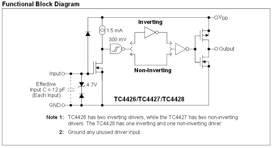
I think that I still have to disagree with this conclusion, I'm afraid. When the outputs are fully on or fully off, there won't be shoot-through, but due to the TC4427 output stage design, there must be a very short period during crossover when both MOSFETs are on. There's 300mV of hysteresis on the inputs, which would at least speed things up and minimise the time that both are on, but again logic tells me that as the output passes through the middle, both MOSFETs must have 6V applied between gate and source, albeit for an extremely short time. The output stage of the TC4427 is a push-pull MOSFET driver, consisting of a P-channel and an N-channel.
This is the block diagram of the driver:-
Edit: Although the block diagram doesn't show it, I assume that the driver has internal protection to prevent shoot-through in it's output stage, but there's no such protection for the external MOSFETs.
The output transistors have an on-resistance of several ohms (10 for the TC4427), limiting the
shoot-through current to under an amp for about 20ns). The point is that power MOSFETs have
3 to 4 orders of magnitude less on-resistance than this driver, so the fact you can live with
shoot-through in lowish-power complimentary FET stages doens't mean you can live with it
for high power.
For 20kHz the TC4427 shoot through averages about 500uA, but 200ns shoot-through in a 24V
5 milliohm half-H-bridge at 20kHz would mean an average of 20A, peak 2.4kA (decoupling caps allowing,
which isn't likely). Its clear that shoot-through in high power stage is completely different beast
to standard complmentary MOS amplifiers because of the ultra-low on-resistances.
MarkT:
Its clear that shoot-through in high power stage is completely different beast
to standard complmentary MOS amplifiers because of the ultra-low on-resistances.
That makes good sense. I was overlooking the 'on' resistance earlier.
raschemmel:
If I used two analog inputs ( with voltage dividers) I MIGHT capture a spike.
An analogRead() is fairly slow. The whole process takes a little over 100uS. I'm not sure how much of that is actual sampling time.
 //This is an example of how you would control 1 stepper

#include <AccelStepper.h>

int motorSpeed = 9600; //maximum steps per second (about 3rps / at 16 microsteps)
int motorAccel = 80000; //steps/second/second to accelerate

int motorDirPin = 2; //digital pin 2
int motorStepPin = 3; //digital pin 3

//set up the accelStepper intance
//the "1" tells it we are using a driver
AccelStepper stepper(1, motorStepPin, motorDirPin);


void setup(){
  stepper.setMaxSpeed(motorSpeed);
  stepper.setSpeed(motorSpeed);
  stepper.setAcceleration(motorAccel);

  stepper.moveTo(32000); //move 32000 steps (should be 10 rev)
}

void loop(){

  //if stepper is at desired location
  if (stepper.distanceToGo() == 0){
    //go the other way the same amount of steps
    //so if current position is 400 steps out, go position -400
    stepper.moveTo(-stepper.currentPosition());
  }


  //these must be called as often as possible to ensure smooth operation
  //any delay will cause jerky motion
  stepper.run();
}
and tested it with my bench Lab supply at 12V. The current was about 250 mA except during the direction reversal when it about doubled for a second. Then I turned off my lab supply and plugged in a LIPO (3S 2200 mAh) (45C) This battery can deliver up to 99A for brief periods. I ran the stepper sketch with a DMM in current mode and it averaged 250 mA (driving two stepper motors in parallel) and increased to 800 to 900 mA during the direction reversal. The sketch runs 3 rps @ 16 microsteps with 200 steps/rev steppers (320016=9600 steps per second)
I have no idea how anyone could calculate the shoot through of the FQP30N06L and the FQP27P06 when both gates are tied together and running of a 12V/0V signal from the TC4427. At 500 us/per Div, the state change of the 12V gate signal was not even 0.1 Div. If I had to guess I would say the
transistion time was less than 100 nS. I have no idea if that's enough time for shoot-through to occur.
The only thing I can say conclusively is that I ran the sketch for about 30 minutes and nothing bad happened. Obviously a DMM is not the right tool to measure it. If I took the whole setup to work I could measure it with a Tek MSO 3054 and current probe . (I would have to get permission from the engineer first. I'm a little hesitant to ask, only because the breadboarded dual h-bridge circuit looks a bit scary. I don't even think I want to post a photo of it, even if does work .
For 20kHz the TC4427 shoot through averages about 500uA, but 200ns shoot-through in a 24V
5 milliohm half-H-bridge at 20kHz would mean an average of 20A, peak 2.4kA (decoupling caps allowing,
which isn't likely). Its clear that shoot-through in high power stage is completely different beast
to standard complmentary MOS amplifiers because of the ultra-low on-resistances.
Ok , now you're scaring me....
I'm thinking that a 7404 has 6 gates or (EVEN NUMBER) . If I cascaded two of these , it could provide 120 nS delay between the P device driver and the N device driver if I added 2 drivers/per H-Bridge and removed the jumper between gates.
[arduino GPIO] => <=
jumper => [P-channel fet driver],
jumper => [7404 daisy chain (12 gates, cascaded)] =>[N-channel fet driver]
I'm not using PWM for my stepper motors but the stepper motor dual H-bridge I made can be reconfigured as two dc motor H-bridges that use PWM. I haven't tried that yet but I have a couple of 12V 1A dc motors. I should give that a try when I get a chance. All I have to do is remove the stepper motor wires from the h-bridges and add a screw terminal strip and run the two H-bidge outputs to that. Then I can easily change the load whenever I want.