I am thinking of making a very bright flashlight! I have decided on using the Cree XHP-70D LED chip.
I thought this would be fairly simple, but it is turning out to be more complicated than I thought (naturally; isn't everything?).
I am trying to figure out the resistor value I would need. I am planning on using a 14.8V 1600mAh 4S 75C drone battery as the power source. I know that a fully charged 4S battery reads 16.8V though.
So... I tried using this calculator, but I am getting confused.
Here is what I put in to the calculator:
I see lots of schematics, found from using words in an internet search thingy, where the LED is driven by different value resistors to produce differing brightness levels.
Don't bother, you can't control an LED of that power with a constant voltage supply and a resistor. As you will have noticed the resistor values come out stupidly small.
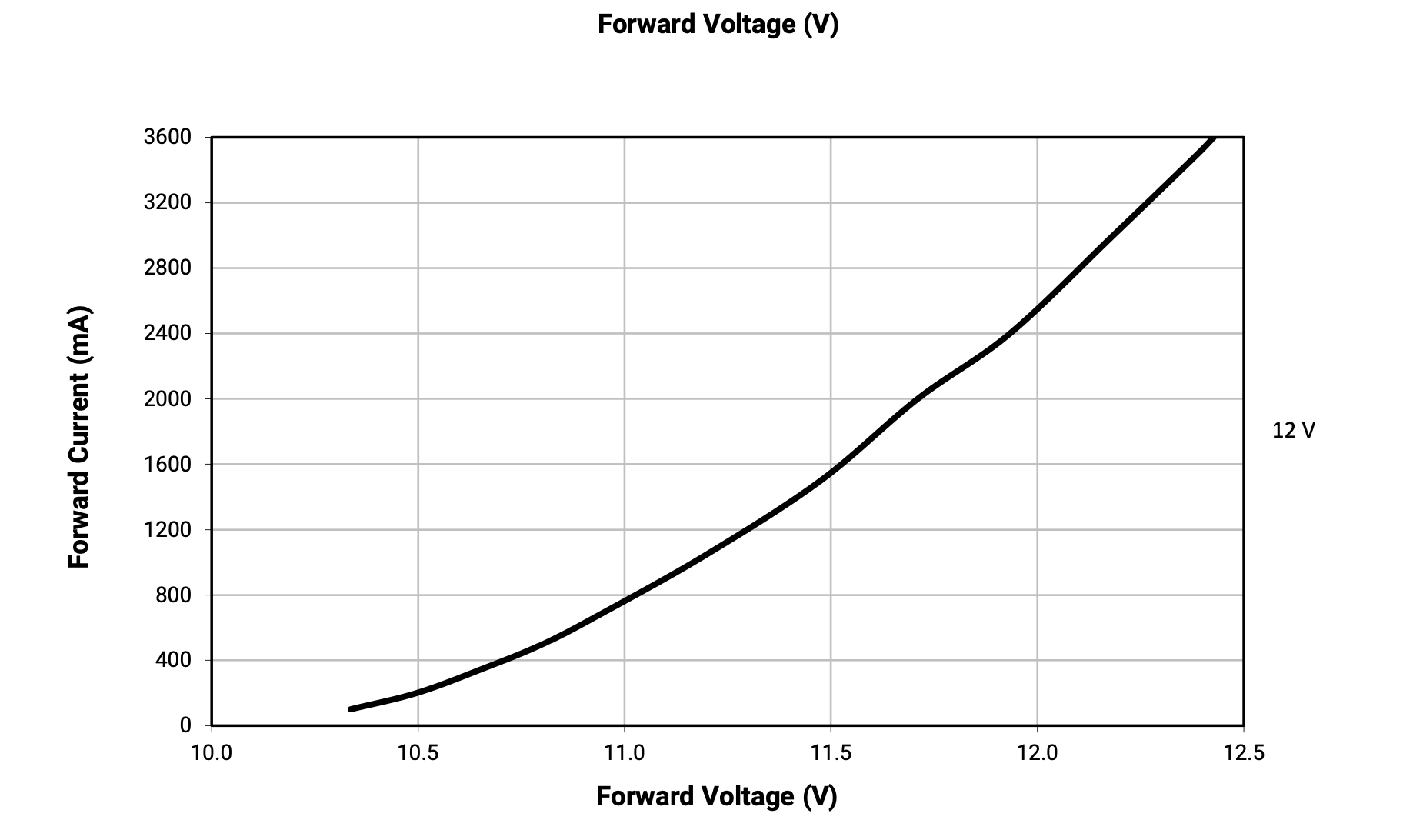
You need to build or buy a constant current supply, because the characteristics of the LED changes over time, age and temperature, and a constant current drive adjusts the supplied voltage so that there is alway a fixed current going through the LED.
Ah, that makes sense! I thought I couldn't just make a 12V constant voltage supply, hence why I posted on here to begin with actually. Or else I would have just hooked up a 12V regulator and called it good.
How would I make a constant current supply?
Edit:
It looks like I could maybe find a LED driver IC that regulates the current and voltage for me!
No... LEDs are normally current controlled and then the voltage "falls into place".
High-power LEDs are not as easy as they may seem...
Look for a "constant current LED driver board". It's not an easy thing to build yourself. They are "switch mode" so they don't heat-up (very much) and they don't waste (very much) power.
The problem with a resistor is that it dissipates power (Wattage = Voltage X Current) so you need a high power resistor which generates heat and wastes power. (That's the voltage dropped across the resistor and the current through it.)
The same thing happens if you use a regular linear regulator and/or MOSFET. The regulator and/or MOSFET will generate heat, and may burn-up. A MOSFET's maximum current rating assumes it's turned fully-on with almost no voltage dropped across it. The current rating for voltage regulators is also tricky... It depends on the voltage dropped across it, and the heatsinking.
A resistor on the MOSFET gate doesn't do what you think...
Correct! An LED runs cooler than a regular incandescent bulb, but internally the LED chip can't handle anything close to the temperature of a tungsten filiment.
I think I am going to use the LED2001 IC for the LED driver. I need some help though with selecting the correct components!
I have selected the correct resistor value for 2.4A (2.32A is the closest I could get) and this comes out to be RS = 0.43Ω. I'm not sure how to calculate for the inductor or capacitors though . The data sheet seems a little convoluted to me .