@StefanL38 In theory you are correct. Depending on SSR quality, it may "lose" some current, even in zero order state. The SSR you talk about would cost more than 100 euro. So, you are correct, and there are acceptable loses, depending on price.
Question to you: Would pins 0 and 1 on Arduino UNO R3 accept 115200 speed?
What I have in mind, as an option, is to use the USB cable I have it plugged in the computer (to read via Putty), and to actually connect it to pins 1 and GND to Arduino. Would that work on 115200?
(This is just for me to know, as ESP32 is on the way.)
Dear All,
I got the ESP32 DEV Module C V4.
Learned how to upload a code in it. (Challenge... but managed.)
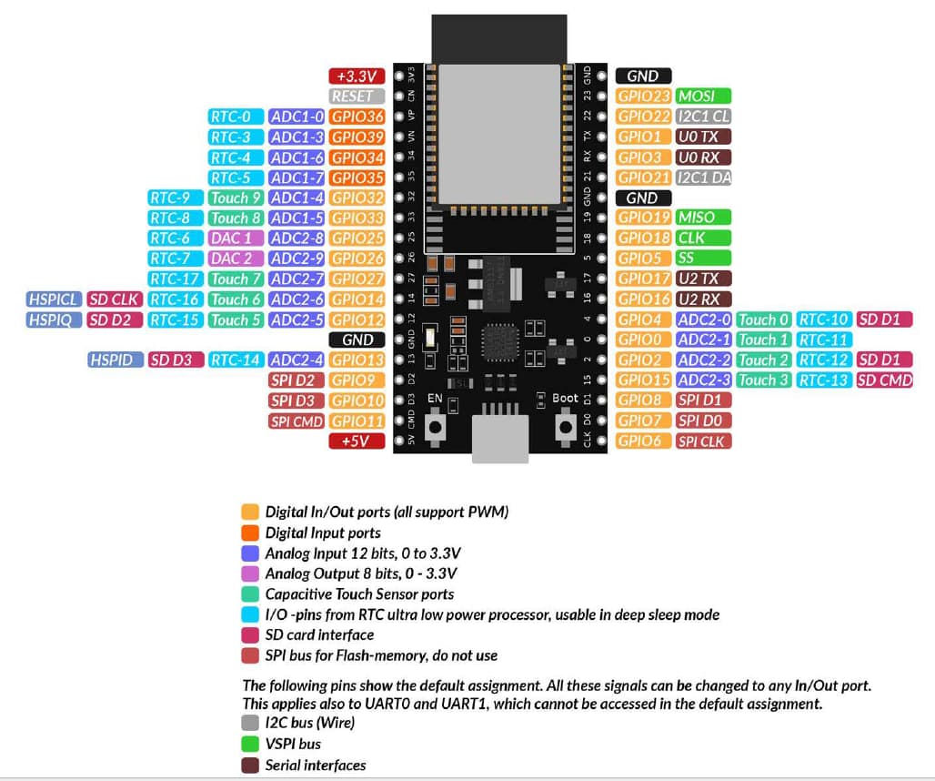
Looks like there are serials at pins 16,17, but also dedicated Rx, Tx.
Can anyone help me to adapt the code so it will work on this new unit?
@bobcousins Wil you be so kind to assist?
After struggling around with ESP32, I am back to your suggestion with Mega.
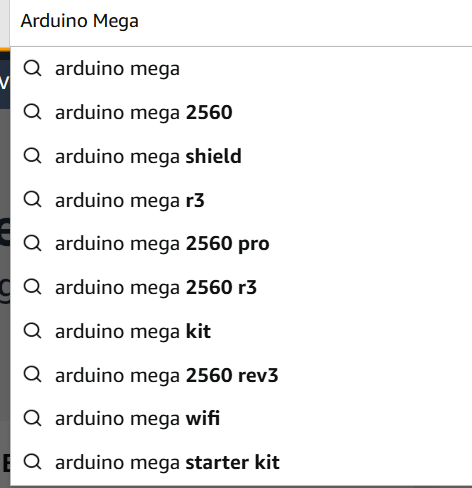
What would be the version?
Which one would support 115200 hardware serial?
No problem to buy, but I would prefer to be sure. Thanks.
If you would be so kind to post your most actual code new.
The users here can help.
Another option is that you look into the ESP32 demo-code for using Serial1 that is posted in post # 60
whenever the microcontroller board is named "Mega" it has a microcontroller of type "Mega" In most cases it will be the Mega 2560.
And all of these boards have a second hardware-serial.
Hardware-serial can easily support 115200 baud. Because the receiving is done by a hardware-UART which works much faster than a software serial on an arduino UNOboard. The UNO has a rather slowly processor-clock of 16 MHz with 8 bit.
While an ESP32 has a 240 MHz processorclock with 32 bit.
Hi
As you now have both an Uno and ESP32, you can very easily emulate this project on your bench, with very few additional components

Using the setup above along with the example sketches that come with the library. Slightly modified, as here...
Upoad this to your Uno. Take care with your Tools board settings and COM port
const char raw[] =
  "/KFM5KAIFA-METER\r\n"
  "\r\n"
  "1-3:0.2.8(40)\r\n"
  "0-0:1.0.0(150117185916W)\r\n"
  "0-0:96.1.1(0000000000000000000000000000000000)\r\n"
  "1-0:1.8.1(000671.578*kWh)\r\n"
  "1-0:1.8.2(000842.472*kWh)\r\n"
  "1-0:2.8.1(000000.000*kWh)\r\n"
  "1-0:2.8.2(000000.000*kWh)\r\n"
  "0-0:96.14.0(0001)\r\n"
  "1-0:1.7.0(00.333*kW)\r\n"
  "1-0:2.7.0(00.000*kW)\r\n"
  "0-0:17.0.0(999.9*kW)\r\n"
  "0-0:96.3.10(1)\r\n"
  "0-0:96.7.21(00008)\r\n"
  "0-0:96.7.9(00007)\r\n"
  "1-0:99.97.0(1)(0-0:96.7.19)(000101000001W)(2147483647*s)\r\n"
  "1-0:32.32.0(00000)\r\n"
  "1-0:32.36.0(00000)\r\n"
  "0-0:96.13.1()\r\n"
  "0-0:96.13.0()\r\n"
  "1-0:31.7.0(001*A)\r\n"
  "1-0:21.7.0(00.332*kW)\r\n"
  "1-0:22.7.0(00.000*kW)\r\n"
  "0-1:24.1.0(003)\r\n"
  "0-1:96.1.0(0000000000000000000000000000000000)\r\n"
  "0-1:24.2.1(150117180000W)(00473.789*m3)\r\n"
  "0-1:24.4.0(1)\r\n"
  "!6F4A\r\n";

uint32_t last;


void setup() {
  // put your setup code here, to run once:
  Serial.begin(115200);
}

void loop() {
  // put your main code here, to run repeatedly:
  if (millis() - last > 1000) {
    Serial.print(raw);
    last = millis();
  }
}
Uno is now printing a simulated output of the Energy meter at 115200 buad on pin 1.
Upload this to your ESP32 again take care of Tools board settings.
#include "dsmr.h"

using MyData = ParsedData<
  /* String */ identification,
  /* String */ p1_version,
  /* String */ timestamp,
  /* String */ equipment_id,
  /* FixedValue */ energy_delivered_tariff1,
  /* FixedValue */ energy_delivered_tariff2,
  /* FixedValue */ energy_returned_tariff1,
  /* FixedValue */ energy_returned_tariff2,
  /* String */ electricity_tariff,
  /* FixedValue */ power_delivered,
  /* FixedValue */ power_returned,
  /* FixedValue */ electricity_threshold,
  /* uint8_t */ electricity_switch_position,
  /* uint32_t */ electricity_failures,
  /* uint32_t */ electricity_long_failures,
  /* String */ electricity_failure_log,
  /* uint32_t */ electricity_sags_l1,
  /* uint32_t */ electricity_sags_l2,
  /* uint32_t */ electricity_sags_l3,
  /* uint32_t */ electricity_swells_l1,
  /* uint32_t */ electricity_swells_l2,
  /* uint32_t */ electricity_swells_l3,
  /* String */ message_short,
  /* String */ message_long,
  /* FixedValue */ voltage_l1,
  /* FixedValue */ voltage_l2,
  /* FixedValue */ voltage_l3,
  /* FixedValue */ current_l1,
  /* FixedValue */ current_l2,
  /* FixedValue */ current_l3,
  /* FixedValue */ power_delivered_l1,
  /* FixedValue */ power_delivered_l2,
  /* FixedValue */ power_delivered_l3,
  /* FixedValue */ power_returned_l1,
  /* FixedValue */ power_returned_l2,
  /* FixedValue */ power_returned_l3,
  /* uint16_t */ gas_device_type,
  /* String */ gas_equipment_id,
  /* uint8_t */ gas_valve_position,
  /* TimestampedFixedValue */ gas_delivered,
  /* uint16_t */ thermal_device_type,
  /* String */ thermal_equipment_id,
  /* uint8_t */ thermal_valve_position,
  /* TimestampedFixedValue */ thermal_delivered,
  /* uint16_t */ water_device_type,
  /* String */ water_equipment_id,
  /* uint8_t */ water_valve_position,
  /* TimestampedFixedValue */ water_delivered,
  /* uint16_t */ slave_device_type,
  /* String */ slave_equipment_id,
  /* uint8_t */ slave_valve_position,
  /* TimestampedFixedValue */ slave_delivered
>;

struct Printer {
  template<typename Item>
  void apply(Item &i) {
    if (i.present()) {
      Serial.print(Item::get_name());
      Serial.print(F(": "));
      Serial.print(i.val());
      Serial.print(Item::unit());
      Serial.println();
    }
  }
};


P1Reader reader(&Serial2, 2);

unsigned long last;

void setup() {
  Serial.begin(115200);
  Serial2.begin(115200, SERIAL_8N1, 16, 17);

  // start a read right away
  reader.enable(true);
  last = millis();
}

void loop () {
  // Allow the reader to check the serial buffer regularly
  reader.loop();

  // Every minute, fire off a one-off reading
  unsigned long now = millis();
  if (now - last > 5000) {
    reader.enable(true);
    last = now;
  }

  if (reader.available()) {
    MyData data;
    String err;
    if (reader.parse(&data, &err)) {
      // Parse succesful, print result
      data.applyEach(Printer());
    } else {
      // Parser error, print error
      Serial.println(err);
    }
  }
}
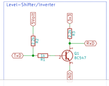
Connect the devices as shown above. The resistors are forming a logic level voltage divider as Uno is a 5V device and ESP32 is 3.3V. Value of resistors not important as long as all the same, +1k Ohm range is fine.
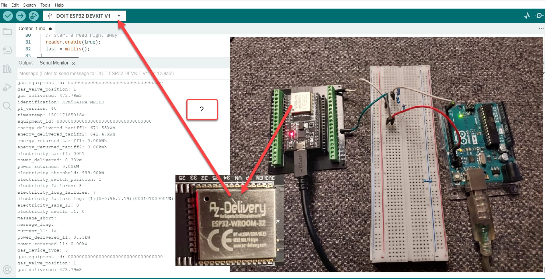
With both devices plugged in and running on your computer, if you open the serial monitor for the COM port that ESP is using. You should see the parsed output every 5 seconds as below...
identification: KFM5KAIFA-METER
p1_version: 40
timestamp: 150117185916W
equipment_id: 0000000000000000000000000000000000
energy_delivered_tariff1: 671.58kWh
energy_delivered_tariff2: 842.47kWh
energy_returned_tariff1: 0.00kWh
energy_returned_tariff2: 0.00kWh
electricity_tariff: 0001
power_delivered: 0.33kW
power_returned: 0.00kW
electricity_threshold: 999.90kW
electricity_switch_position: 1
electricity_failures: 8
electricity_long_failures: 7
electricity_failure_log: (1)(0-0:96.7.19)(000101000001W)(2147483647*s)
electricity_sags_l1: 0
electricity_swells_l1: 0
message_short:
message_long:
current_l1: 1A
power_delivered_l1: 0.33kW
power_returned_l1: 0.00kW
gas_device_type: 3
gas_equipment_id: 0000000000000000000000000000000000
gas_valve_position: 1
gas_delivered: 473.79m3
Edit: Pin 1 on Uno is TX to voltage divider
Pin 16 on ESP is Serial2 RX from voltage divider
Edit2: Get the above working, then we can discuss extraction of the 'items' you need, file storage, csv files etc.
2 Likes
@indev2
Done, and indeed I get similar info as you.
(On the ESP32 I have is mentioned V4. Could not find it in library so I've selected Dev Kit V1)
Does it means now that if I change Uno with signal from energy meter, then I shall get my data? I will try it.
PS. You say that ESP32 is 3.3V. Correct. However, the one I have have 5V at the close left pin.
Well you can certainly try, there maybe problems with the inverted output, and do keep the voltage divider in circuit. How are you sending the output trigger?
Yes all esp's are 3.3V. The 5V pin is just a line out of the 5V usb in. And don't worry too much over the V4 designation, the default Dev Kit V1 is usually OK.
Meaning the 3 resistors you indicated? Even I have the inverter?
Checkmate! No clue what you mean. Sorry.
Without inverter, nothing. (I will try again this one with 3 resistors version.)
With inverter, something...
Do you need an export of the strings I get with Putty?
What strings are you getting in Putty?
Can you post a copy?
The inverter will be outputting 5V logic. The other option (schematic) you posted was for 3.3V. You can use your current inverter if you put the output through the 3 resistor divider.
This is what is coming out.
Tomorrow the divider with or without inverter.
/FLU5\253967035_D
0-0:96.1.4(50221)
1-0:94.32.1(230)
0-0:96.1.1(3153414733323030333534343634)
0-0:96.1.2()
0-0:1.0.0(250228224742W)
1-0:1.8.1(000146.979kWh)
1-0:1.8.2(000155.289kWh)
1-0:2.8.1(000105.584kWh)
1-0:2.8.2(000027.183kWh)
0-0:96.14.0(0002)
1-0:1.4.0(00.034kW)
1-0:1.6.0(250222134500W)(04.202kW)
0-0:98.1.0(2)(1-0:1.6.0)(1-0:1.6.0)(241101000000W)(241001000000S)(00.000kW)(250201000000W)(250121203000W)(04.928kW)
1-0:1.7.0(00.197kW)
1-0:2.7.0(00.000kW)
1-0:21.7.0(00.249kW)
1-0:41.7.0(00.000kW)
1-0:61.7.0(00.000kW)
1-0:22.7.0(00.000kW)
1-0:42.7.0(00.000kW)
1-0:62.7.0(00.051kW)
1-0:32.7.0(230.5V)
1-0:52.7.0(000.0V)
1-0:72.7.0(230.0V)
1-0:31.7.0(001.41A)
1-0:51.7.0(001.19A)
1-0:71.7.0(001.07A)
0-0:96.3.10(1)
0-0:17.0.0(99.999kW)
1-0:31.4.0(999.99A)
0-1:96.3.10(0)
0-2:96.3.10(0)
0-3:96.3.10(0)
0-4:96.3.10(0)
0-0:96.13.0()
0-1:24.1.0(007)
0-1:96.1.1(3853455430303230303534323131)
0-1:96.1.2(000000000000000000)
0-1:24.2.1(250228224300W)(00017.027*m3)
!1066 (This one changes every time)
Excellent grab!
I'll run that through our Uno/ESP rig, tomorrow though time we took a break ![]()
Edit: I found some cool stuff here
Smart meter reader - Opencircuit
Edit2:
From the above
Viorel_C,
Hello, glad to see that you have had some success.
That last line is a checksum.
If any of the rest of the data changes, then that will be re-calculated and change accordingly.
@indev2 I've done the tests with or without divider. Direct or via inverter.
With divider, nothing.
I would like to draw you attention to multiple energy meters reading libraries available on the web. Some of them general, some of them NL-BE, some of them BE.
As I have no clue how to understand and use these libraries, I just point out on these differences.
Here is for instance one example:
This one would have for instance dsmr2.h file, instead the one you used.
If I load / use these, instead dsmr.h you used, then I get compilation errors, which I have no clue how to deal with.
Along my time, I get crossed with serial links. And, yes, there were "templates".
But I could see what and when to use.
For an NMEA communication, there were headers and formats.
So, I could see what was via putty and compare with what was in the "library".
Then, when programing, I was able to direct each number behind a specific header where to go.
So easy...
In this case with Arduino, it looks lot more complicated.
I see libraries, but could not (yet) cope with how to use them. I will just keep reading.
From this posting I can conclude that you haven't understood yet the seriousness of the 3.3V-thing
5V can DAMAGE your ESP32 !
you might have had just luck that your ESP32 is not yet destroyed
imagine the following
a bicycle-tire usually has a pressure of 2 to 4 bar. These race-bicycles have 10 bar.
Now imagine you want to pressurise this bicycle-tire with 100 bar
What will happen? The tire will explode at 15 to 20 bar !
You see a small inscription somewhere like "5V" and then you think "ah, the microcontroller is suitable for 5V after all.
No way!
You have a naivety coupled with ignorance that will cause you to destroy several microcontrollers.
The IO pins REALLY only tolerate 3.3V
It's pure luck if the ESP32 still works.
Since you are obviously not ready to learn the basics of electrical engineering, you should ask in the forum before each new test on the real hardware whether this is possible. Or whether components could be destroyed.
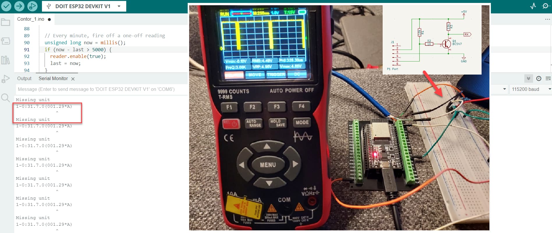
@StefanL38 What about asking to show how the measurement is at port 16 of ESP32?
That would be x10 positive approach.
Here it is. Would this give you the answers?
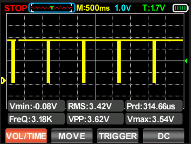
So, the 3.54V should not give any issue to ESP32... I assume.
I've applied diagram from post#76, so, 5V is applied to the energy meter, and 3.3 to BC547 to invert the signal. GND is commune.
I know you want to help, with open heart. So, please do.
Hello viorel_c
I've split your question (and the replies) into a dedicated topic. Please do not hijack an existing topic.
1 Like
New topic, I won't ask.
And finally....
P1Parser: OK!

identification: FLU5⸮967035_D
p1_version_be: 50221
timestamp: 250228224742W
equipment_id: 3153414733323030333534343634
energy_delivered_tariff1: 146.98kWh
energy_delivered_tariff2: 155.29kWh
energy_returned_tariff1: 105.58kWh
energy_returned_tariff2: 27.18kWh
electricity_tariff: 0002
power_delivered: 0.20kW
power_returned: 0.00kW
electricity_threshold: 100.00kW
electricity_switch_position: 1
message_long:
voltage_l1: 230.50V
voltage_l2: 0.00V
voltage_l3: 230.00V
current_l1: 1.41A
current_l2: 1.19A
current_l3: 1.07A
power_delivered_l1: 0.25kW
power_delivered_l2: 0.00kW
power_delivered_l3: 0.00kW
power_returned_l1: 0.00kW
power_returned_l2: 0.00kW
power_returned_l3: 0.05kW
mbus1_device_type: 7
mbus1_equipment_id_ntc: 3853455430303230303534323131
mbus1_delivered: 17.03m3
Yes that is your data. Ta dah.....
Note that @viorel_c did not create a new topic, I did ![]() See post #78.
See post #78.
1 Like
What pin (energy meter) are you applying 5V to?