I want to add a digital speed readout to my car's traditional instrument cluster. And I'd rather avoid using GPS or sniffing the CAN bus, or worse, something like measuring ABS sensors directly, etc. Naturally, I thought it'd be feasible to re-interpret the speed stepper's waveform. That sounds safe and simple enough for me. Or at least it did until today.
So, I got a cheap instrument cluster to experiment with. It has 4-wire (bipolar?) steppers similar to those that my actual car's cluster has. I see no separate driver ICs, all lines go straight from the cluster's CPU.
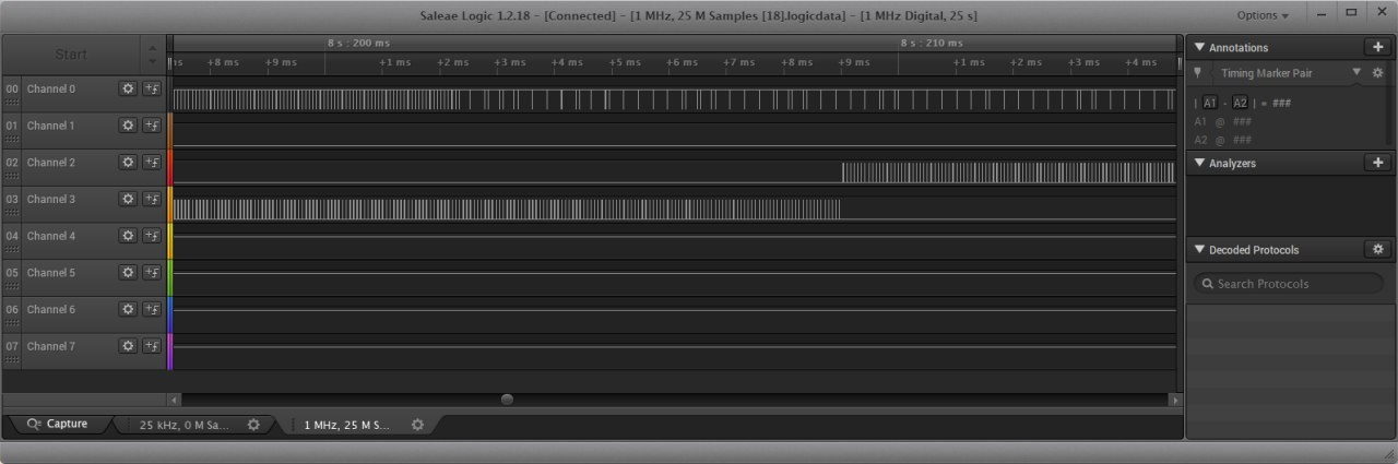
Now, the problem is that upon closer inspection, the waveform looks kinda PWM-ish with a frequency of around 15 kHz.
If you are posting a picture of the voltage at the coils of the stepper motor then what you are seeing is the sequence of pulses needed to make the motor move. When the motor gets to the desired position the pulsing should stop.
I'm not sure whether it would be practical to interpret those pulses to determine the value displayed by the needle of the instrument. You would have to detect (at vehicle startup) when the motor is moved to the ZERO or HOME position and from then on keep accurate count of the motor-steps up and down.
Note, also, that the position of the motor only represents speed because the drivers eyes see the speed-number that the needle is pointing at.
Getting data from the CAN bus would be much more reliable, and while I am not familiar with it myself (I don't have a car), there seem to be lots of Forum Threads about the CAN system.
Hi,
Welcome to the forum.
Think you have the wrong idea about how steppers are driven.
The signals are only present when the stepper has to move, making it move in a direction and certain number of steps.
The air-cored automotive steppers that you want to monitor are not driven by the normal standard step, step, step pulses but PWM signals to produce the smooth analog meter type characteristic.
Interpreting those signals would not be feasible.
What have you got against GPS or the many CanBus projects that are about.
I fact you can get a ready made unit that projects your speed on your windscreen.
Google.... car digital on screen speedometer display
Sorry, I'd rather not discuss pros and cons of other solutions here. Perhaps, I should've started this thread in a different more specialized forum.
So far this info in particular sounds relevant, useful and interesting:
The air-cored automotive steppers that you want to monitor are not driven by the normal standard step, step, step pulses but PWM signals to produce the smooth analog meter type characteristic.
I'll try to google something up in this direction, thank you =)
I don't quite understand why counting stepper pulses would not be feasible and reliable though. Can't a microcontroller be faster and more precise than some simple mechanical linkage? What am I missing here?
yegorp:
I don't quite understand why counting stepper pulses would not be feasible and reliable though. Can't a microcontroller be faster and more precise than some simple mechanical linkage? What am I missing here?
Feel free to try it. The Arduino system is great for learning-by-doing.
IMHO it will involve a lot of programming effort and testing compared to doing the job using CAN bus.
I used its test mode (power up while holding the reset button), so the gauge (all gauges, actually) went back and forth three times before settling at zero.
Hi,
Okay, so did the trace stop showing pulses when the gauges settled at zero?
It may do because it is zero, but I would say if the gauge was showing a constant reading other than zero, you would be seeing pulse signals all the time.
so did the trace stop showing pulses when the gauges settled at zero?
It kept showing pulses even after the gauge had settled at zero. In this case I guess the zero is no special from a positive constant requiring "pulse signals all the time".
So how should I approach interpreting such a signal by an Arduino? Can I somehow ignore the PWM-ness of it and only count the coarse steps?
And by the way, I've managed to read the data from the CAN bus months ago. But this time I want to capture the stepper signal specifically. If I can't do it in a reliable enough way, that's when I'll have to reside to CAN.