I spent some time yesterday trying to get interrupts to work. It took longer than it should have, I think.
I ran into two problems. First, I don't know what a "pin number" is. If I call an API like pinMode() or digitalWrite(), the documentation says the pin parameter is meant to be "the Arduino pin number".
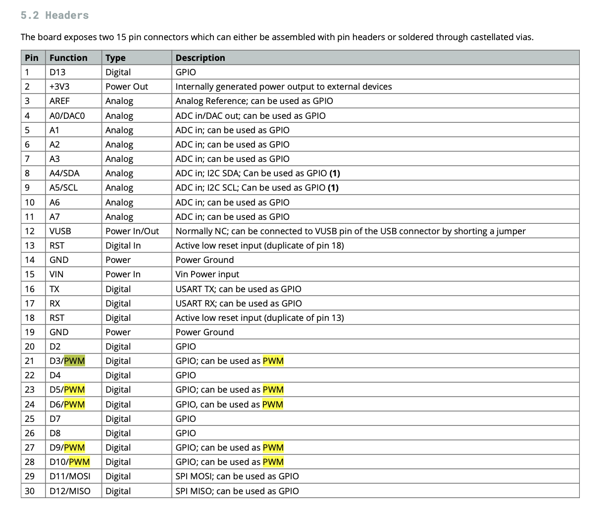
What is this number? I thought it would be the IC pin number, 1 thru 30 for the Nano 33 IoT module. Then, I realized there's no pin 1 identification on my board.
I looks like the number really is the ... well, it seems to be something that doesn't have a name. If I want to use the pin marked "~D2" in the pinout diagram as an output, I'd call pinMode(2, OUTPTUT). Why does "~D2" have a tilde in its name when other digital pins don't?
What about other pins, like the analog inputs and outputs, or interrupts? How are they numbered and identified in code?
I wanted to use "D7" for my interrupt input. The pinout says it is also "INT[6]". Do the square brackets have any significance?
Something I read somewhere says I should use digitalPinToInterrupt() to translate a pin number to an interrupt pin number. So I coded this:
  int pinNumber = 7;
  pinMode(pinNumber, INPUT);
  attachInterrupt(digitalPinToInterrupt(pinNumber), crossingHandler, RISING);
but it didn't work. I spent a lot of time fooling with this, and discovered that digitalPinToInterrupt() outputs whatever its input parameter is so it doesn't seem to be doing any translation at all.
Eventually, I found this post which says that only pins 2, 3, 9, 10, and 11 work as external interrupts. Why do so many other pins show an "INT[n]" designation in the pinout? Oddly, several pins show the same number for n. For example, three different pins show "INT[2]". Why is it so?
How are the pin assignments on the pinout diagram meant to be read? How do I translate them to parameters that I can pass the API?