Ahh, I did not realise that a relay module may have different attributes from a relay.
Unfortunately I do not have the datasheet -currently requesting one from the seller.
Will update here once I get it.
@Paul_B
Sorry could you share with me the implications of connecting a 70Ohm relay to an ESP output?
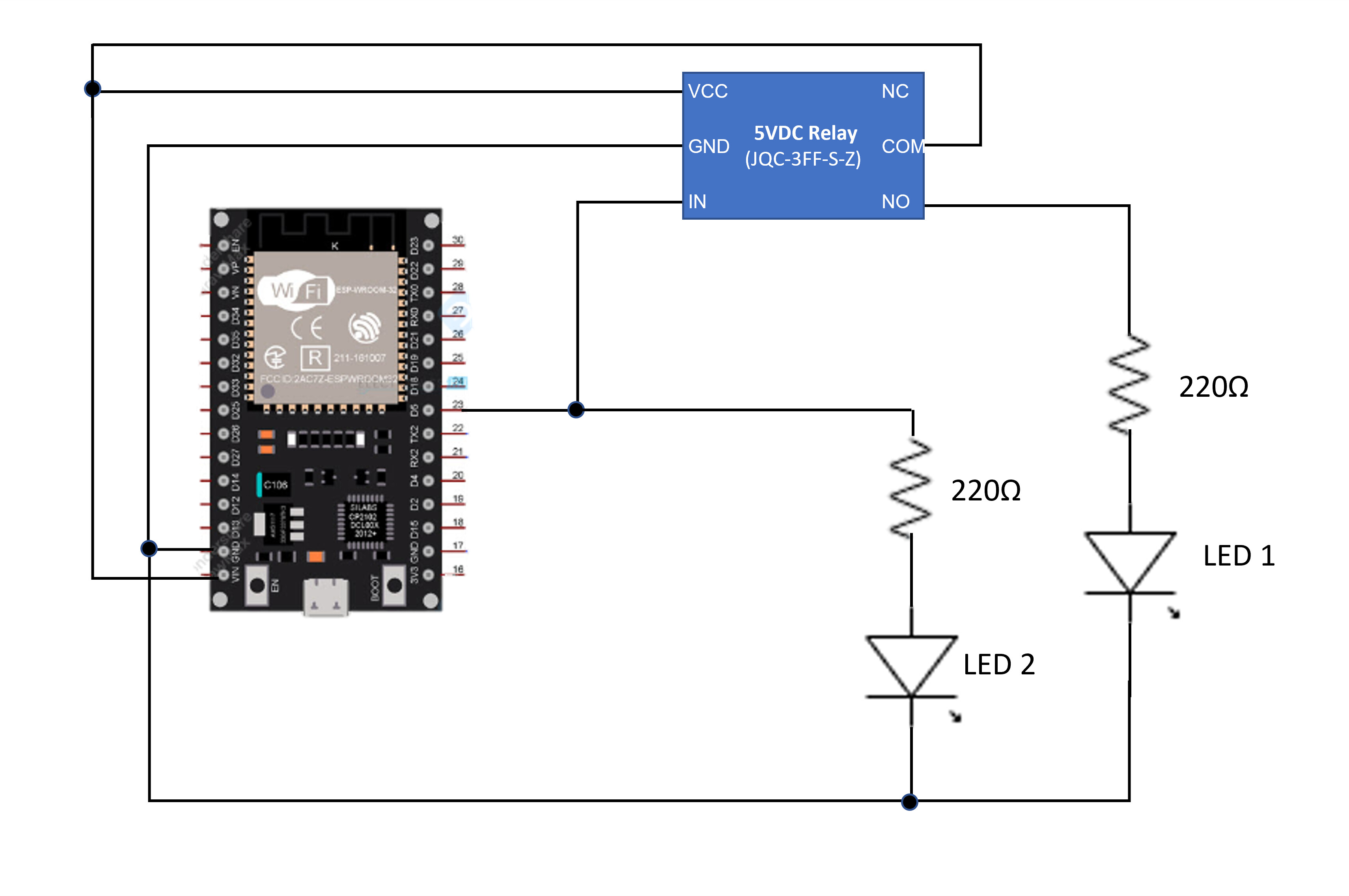
What you meant was that the relay is always on or in fact "triggered" and illuminating your "LED 1".
This is a "low level trigger" relay module and when powered from 5 V (as it must be), connecting its "IN" terminal directly to an ESP I/O means that the "IN" terminal is always LOW since 3.3 V is lower than 5 V.
Just connect LED 2 - with no resistor - between the ESP I/O pin and the relay "IN" - with the LED anode to the relay module.
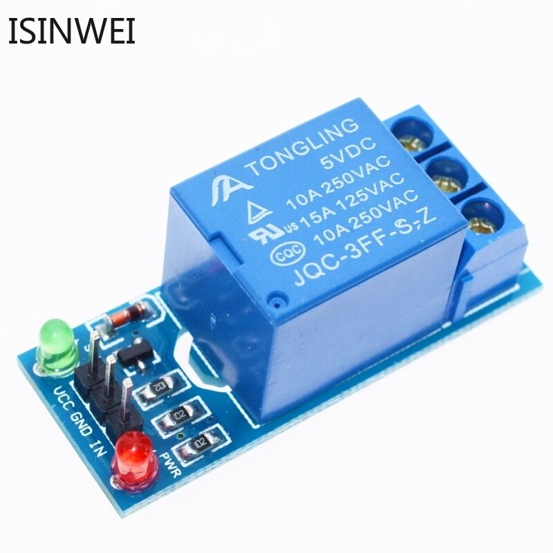
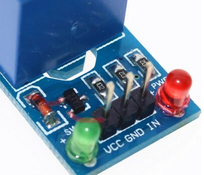
I think one of the board's LEDs is for VCC present and the other is likely an Input indicator (no external LED required).
It also looks like it has a transistor there (common emitter? IDK), not an opto-device.
Yeah, its low level trigger.
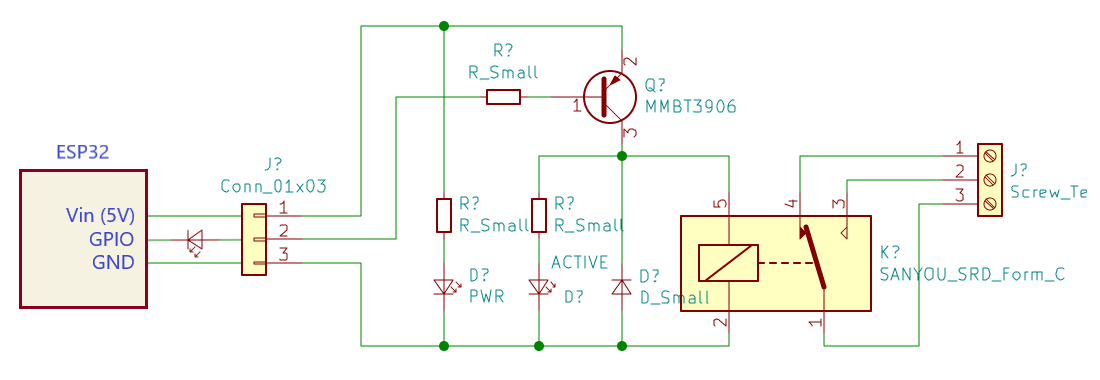
The transistor is PNP switching the high side of the relay coil. Below I've highlighted the path of VCC to the PNP to the relay coil +''ve terminal on the PCB:
The base transistor is 1K.
Possible solution:
I suggest trying this with an LED to drop the relay "IN" voltage ... LED anode to IN, LED cathode to ESP32 output pin. The LED will illuminate and the relay should energize when the ESP32 output pin goes LOW. Use Vin (5V) from ESP32 connected to relay module VCC
Actually it depends on which relay module you use. Is the relay board as same as the board used in the tutorial? Some relay boards. Some relay boards have in built logic level converter. They can trigger at 3.3V from ESP32. But for the other ordinary relay modules, logic level converter must be added as shown here: ESP 32 Connect 5V Relay via Logic Level Converter (ESP32) - YouTube
Late to the party, but fundamental question - can you in fact use the "VIN" pin on that device as an OUTPUT? Because unless there's more to your circuit than shown, that's what you're doing.
As for the 5V, 3.3V discussion, here's a different viewpoint. When the GPIO connected to the relay is not "LOW", i.e. not sinking current, it is driven "HIGH"; but, it is exposed to the voltage attached to other devices at it's output. That voltage will be 5V, assuming you resolve my first question successfully. Is that 5V acceptable to the output ratings of the 3.3VDC GPIO pin? IIRC, they're not tolerant of voltages exceeding the supply voltage of the device, in this case 3.3 VDC.