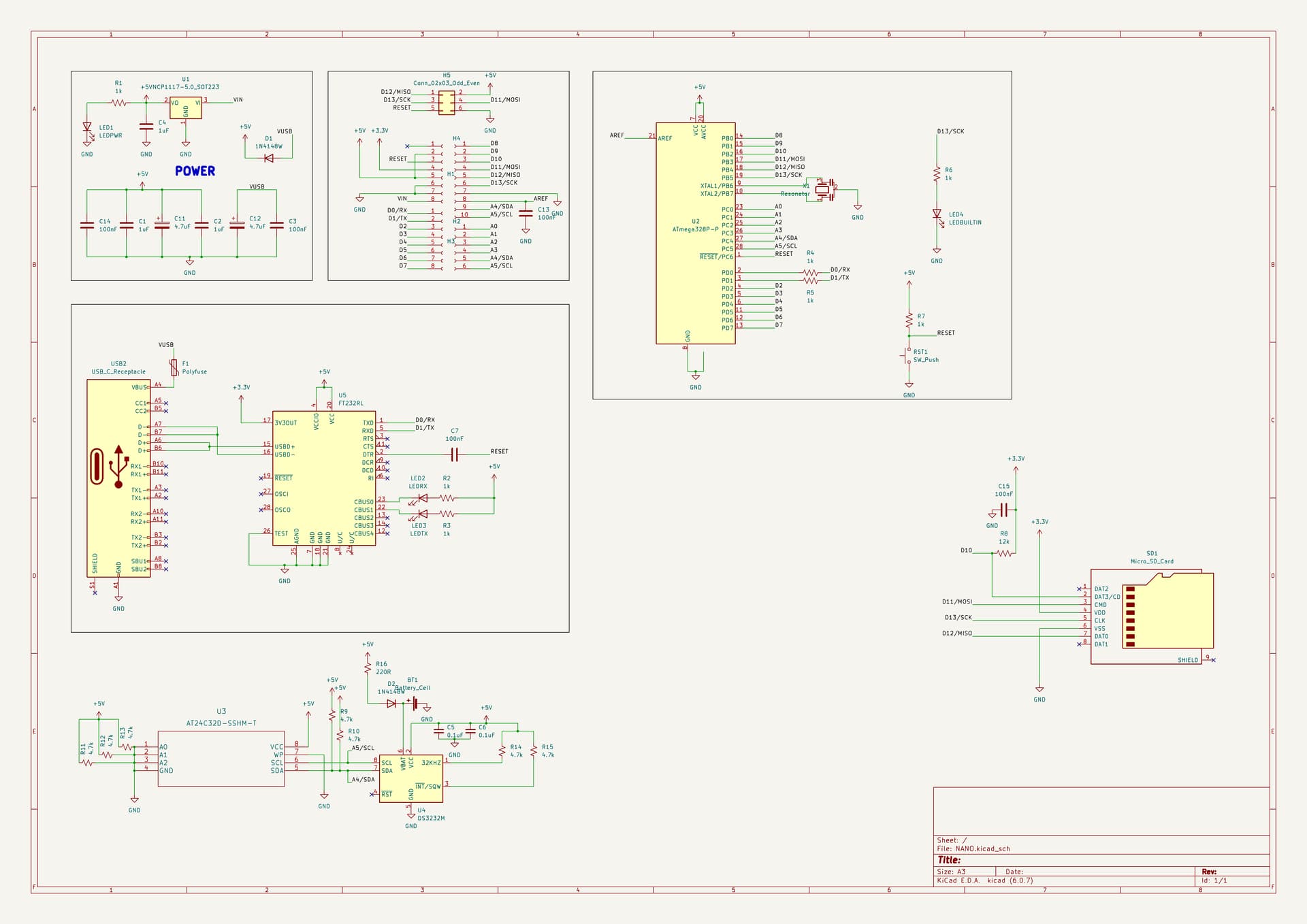
I did A KiCad one as well.

Don't blame Fritzing. @outbackhut is a beginner at schematics too. Whatever drawing tool was used, it would probably have looked just as spider-web like!
QED.
My tips for drawing schematics are
- The position, size and orientation of components on a schematic don't have to bear any resemblance to reality. Clearly communicating the connections between them is the only important thing. So place and rotate them any way you can to reduce long or criss-crossing connections.
- Use as many "Power" symbols like 5V, 3V3, GND as you like, close to each component that needs them, to avoid having those connections snaking all over the schematic.
1 Like
What is that?
How does that go (in KiCAD, as you can't do that in Fritzing) when you turn the Schematic into a PCB? Does KiCAD automatically recognize those as connected together?
quod erat demonstrandum
Yes, you can.
I don't know KiCAD, but I'm sure it will recognise them as connected.
1 Like
In my day, we read that as Quite Easily Done ![]()
As PaulRB said, use lots of power symbols and GND symbols. It will make the schematic much easier to read.
And if I may add some additional thoughts:
Keep power pointed up and GND pointed down.
Keep all writing in one orientation, as much as possible.
Use netports/labels. They will automatically connect with each other. Most software will let you know if you have left anything not connected.
Leave reminders for yourself.
Here is an example that I made in EasyEDA: I gave the SCL, etc pins labels; wires (rat lines) will be added by EasyEDA at the time of conversion to PCB. The various Out net labels lead to a different sheet. C1 is in the same group as the expander, to remind me to put it close to U1's VDD pin.

1 Like


I believe the first circuit will work if the processor driving SCK, MOSI and CS is running at 3.3V. If those lines are driven at 5V, then it won't work. Actually I should say it shouldn't work. The typical full-size SD card module has essentially this circuit, and it is widely represented as being appropriate for Unos and Nanos, and apparently is widely used that way, successfully most of the time, but not always. But it still isn't right.
However, I don't think you need R16. My memory is that SD cards have internal 50K (nominal) pullup resistors on that pin. But if you do use R16, 10K or higher would probably be more appropriate. It's not a line that switches a lot.
I don't think the second circuit is good. First, those bidirectional level shifters are notorious for not being very forgiving. And besides, you don't need bidirectional. Three of the SPI lines go one way, and MISO goes the other way, but none of them needs to be bidirectional. And specifically, MISO doesn't need to be translated at all. So you just need a buffer chip that converts 5V to 3.3V. I think Adafruit uses the 74HC4050. The typical microSD module from the Far East uses the 74LVC125A.
More important, it looks like MISO is always active, which is exactly what you don't want if two cards are present.
I don't know what the box labeled TF is. You have another box labeled SD Socket.
Q1 would need to switch 3.3V, not Vcc, to the SD card's Vcc. It is a 3.3V device.
I'm still puzzled by the pinout of the block labeled SD/SDSocket.
I got it from here:
http://wiki.sunfounder.cc/index.php?title=SD/TF_Card_Reader_Module
I'll use the top one.
I was hoping to use that first circuit with a micro SD card. I hate using full size SD cards as they are way too big.
Can I put resistors on the lines then, or must I use logic level converters?
I've never tried using resistors to translate voltage, but I suppose it would work.
It wouldn't muddy the data coming to and from the Arduino?
Well, you would have a resistor in series between the Arduino pin and the SD card pin, and another resistor between the SD card pin and ground. The potential problem with doing it this way is that it could slow things down so that the SPI speed would have to be reduced to work reliably. I don't know how to calculate whether that problem is likely to arise. It depends on the characteristics of the SD card pins., which could vary from brand to brand.
So a logic level converter doesn't do this?
I don't think so. But, it's an extra chip.
Have you given up using your two original SD card devices?
1 Like
Yes. Now I'm trying to make a custom Uno that has an in-built SD card, and I want to be able to use the SPI for other things as well as the built in SD card.
This is the work-in-progress schematic so far:
Well if you're building something from scratch, I'd suggest you use a buffer-type translator chip for MOSI, SCK and CS. MISO would just connect directly. That would give you full speed with no question. And I don't think you need R8.
The translator chip would also use less current than the resistor dividers.
Do you have any specific recommendations?
I listed two alternatives in post #48.
Ah, I missed that. Thanks.
This should do, shouldn't it?
Yes, but that part also comes in a DIP package that would work in a breadboard, which would be convenient for testing.
It has six gates, but you only need three. You could just tie the inputs of the unused gates high or low to keep them from floating.