I'm new to Arduino, and this is my first project. The project is to read various sensors and write data to a micro SD card. I have searched and read a number of "SD card doesn't work" postings, and haven't found anything that answers my question or solves my issue.
In short, when running the example card sketch in the Arduino IDE, the card fails to initialize. In troubleshooting I find some odd voltages on the card reader pins.
I ran the example sketch, changing CS from pin 10 (as in the UNO) to pin 53 according to documentation on the Mega and multiple postings on the subject.
The card is formatted to fat32 and works fine in my laptop. There are currently no files on it, but I was able to save and open files using the laptop.
I've checked the wiring multiple times:
VCC Mega 3.3V
GND GND
MISO pin 50
MOSI pin 51
CLK pin 52
CS pin 53
To further check the wiring, I checked the voltages.
VCC 3.3V.
GND 0
MISO 3.3
MOSI 4.9
CLK 0
CS 4.9
I then ran Cardinfo, and got these values:
VCC 4.15V
GND 0
MISO 4.15
MOSI 4.8
CLK 0
CS 4.8
Those voltages persisted after resetting the Mega, and after disconnecting and reconnecting the USB (without uploading a sketch). I then left the hardware and did some searching for documentation on the expected values and came back to it after about an hour. The voltages have returned to their original values, but jump to the higher ones on running a sketch, then persist at those higher values.
So, what's going on? Are these expected values? I haven't found documentation on the SD device that would tell me; where would I look for that? Why the change after running a sketch and initializing the system?
Could you elaborate a little more please (see "new to Arduino" above. Or perhaps I should have said "new to electronics" instead).
I am powering the SD board with 3.3 V, so I assume you mean that I have to convert the other pins instead? All of them, or only CS and MOSI; the ones that were showing 4.9V. By 3V, do you mean 3.0V or 3.3V? I found this unit to convert 5-3.3 and vice versa, but didn't find a 5.0-3.0.
ALL of the connecting pins. Use a bidirectional logic level shifter like this one.
This is not specific to "Arduino", matching voltage levels is basic electronics. It is much better to use 3.3V Arduinos with 3.3V sensors and devices, as 5V logic is rapidly becoming a thing of the past.
"3V" in this context is 3.3
It's like the '3V' terminal on your Mega, it's nominally 3.3V.
All of the signal lines require level shifting.
The device you show in Post No.3 should be sufficient.
A card/board like what I linked to may prove easier, less hassle, at this point.
On the qkits board? Ask them.
On that 'level-shifter'? I think it features the MOSFET design that Philips came up with several years ago - primarily for their I2C stuff - but it's useful in general.
Thank you jremington and runaway_pancake for your help, and patience with a newbie.
I now have a logic shifter in place and voltages are back to 3.3V on VCC, CS, MISO and MOSI. Unfortunately, Cardinfo still gives "initialization failed".
I've checked continuity and correct connections on the wiring. Card is inserted and fully functional. Chipselect changed in Cardinfo to the correct pin (53) for Mega. Did I damage the card reader when it was powered without the logic shifters? Is there anything else I can check to see if the module is working correctly?
There aren't any active components on the qkits board so it's probably ok.
Barring any wiring fault, I'd suspect it's the microSD doesn't take kindly to 5V.
Barring any wiring fault, I'd suspect it's the microSD doesn't take kindly to 5V.
The card works fine in my laptop. No errors on installing it, I can save, open and delete files on it. "Properties" shows fat32. I don't have another card to test right now. I'll get one tomorrow.
Comment 11 in this post SD card using ICSP pins - #11 by CrossRoads talks about mismatch between the current the Arduino can supply vs that required by the SD card. Is this relevant? If I'm interpreting it correctly, the problem is with the signal voltages not the supply voltage, so I don't think it applies to my case(?)
Even with your full wiring description, posting a wiring diagram will be more descriptive at a glance. Also, include the minimal sketch you are using.
Sketch is below. It's the example one from the IDE. I've trimmed all the stuff after initialization as that's where I'm getting the failure, but the full version (with pin 10 -> pin53) gives the same results.
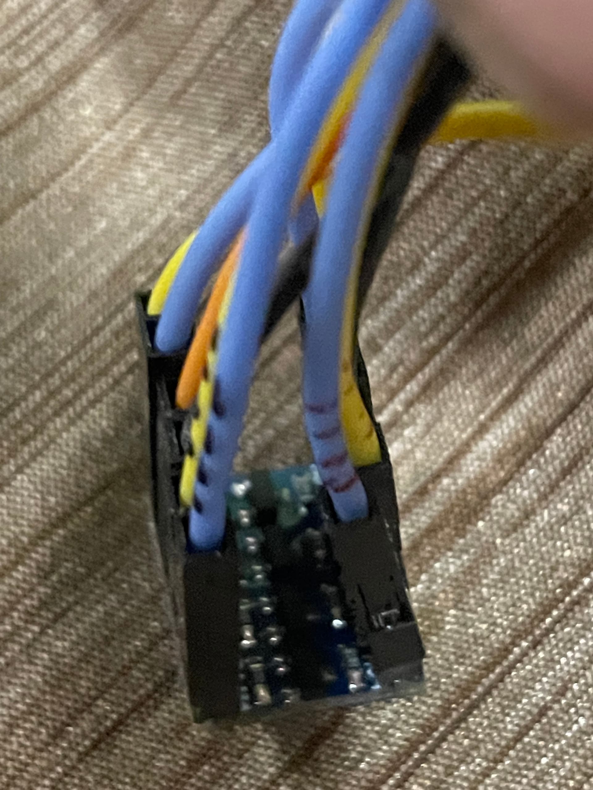
Wiring photos and sketch below. Note 5V is red, 3.3V is orange, ground is black:
/*
  SD card test

  This example shows how use the utility libraries on which the
  SD library is based in order to get info about your SD card.
  Very useful for testing a card when you're not sure whether its working or not.
  Pin numbers reflect the default SPI pins for Uno and Nano models. (mega in brackets)
  The circuit:
    SD card attached to SPI bus as follows:
 ** SDO - pin 11 (50) on Arduino Uno/Duemilanove/Diecimila
 ** SDI - pin 12 (51) on Arduino Uno/Duemilanove/Diecimila
 ** CLK - pin 13 (52) on Arduino Uno/Duemilanove/Diecimila
 ** CS - (53) depends on your SD card shield or module.
 		Pin 10 (53) used here for consistency with other Arduino examples

  created  28 Mar 2011
  by Limor Fried
  modified 24 July 2020
  by Tom Igoe
  modified for mega use, truncated past initialization step.
*/

#include <SPI.h>
#include <SD.h>

const int chipSelect = 53;

void setup() {
  Serial.begin(9600);
  while (!Serial) {
    ; // wait for serial port to connect. Needed for native USB port only
  }


  Serial.print("\nInitializing SD card...");

  // we'll use the initialization code from the utility libraries
  // since we're just testing if the card is working!
  if (!card.init(SPI_HALF_SPEED, chipSelect)) {
    Serial.println("initialization failed. Things to check:");
    Serial.println("* is a card inserted?");
    Serial.println("* is your wiring correct?");
    Serial.println("* did you change the chipSelect pin to match your shield or module?");
    Serial.println("Note: press reset button on the board and reopen this Serial Monitor after fixing your issue!");
    while (1);
  } else {
    Serial.println("Wiring is correct and a card is present.");
  }


}

void loop(void) {
}
... unless you check that the revised sketch compiles properly. Which I didn't do. Sorry. Corrected sketch below, and pencil diagram. I did check that this version of the sketch generates the same error.
/*
  SD card test

  This example shows how use the utility libraries on which the
  SD library is based in order to get info about your SD card.
  Very useful for testing a card when you're not sure whether its working or not.
  Pin numbers reflect the default SPI pins for Uno and Nano models. (mega in brackets)
  The circuit:
    SD card attached to SPI bus as follows:
 ** SDO - pin 11 (50) on Arduino Uno/Duemilanove/Diecimila
 ** SDI - pin 12 (51) on Arduino Uno/Duemilanove/Diecimila
 ** CLK - pin 13 (52) on Arduino Uno/Duemilanove/Diecimila
 ** CS - (53) depends on your SD card shield or module.
 		Pin 10 (53) used here for consistency with other Arduino examples

  created  28 Mar 2011
  by Limor Fried
  modified 24 July 2020
  by Tom Igoe
  modified for mega use, truncated past initialization step.
*/

#include <SPI.h>
#include <SD.h>
Sd2Card card;
const int chipSelect = 53;

void setup() {
  Serial.begin(9600);
  while (!Serial) {
    ; // wait for serial port to connect. Needed for native USB port only
  }


  Serial.print("\nInitializing SD card...");

  // we'll use the initialization code from the utility libraries
  // since we're just testing if the card is working!
  if (!card.init(SPI_HALF_SPEED, chipSelect)) {
    Serial.println("initialization failed. Things to check:");
    Serial.println("* is a card inserted?");
    Serial.println("* is your wiring correct?");
    Serial.println("* did you change the chipSelect pin to match your shield or module?");
    Serial.println("Note: press reset button on the board and reopen this Serial Monitor after fixing your issue!");
    while (1);
  } else {
    Serial.println("Wiring is correct and a card is present.");
  }


}

void loop(void) {
}
That shows pin 50 (for example) as CIPO, just to add further confusion. (Top hit for CIPO, MISO, SDI is a rant about the number of acronyms and similar confusion!)
So isn't CIPO = Controller Out Peripheral In = Master Out Slave In = pin 50. My SD card has the labels MISO and MOSI, so as long as these translate to CIPO and COPI respectively I should be ok, and I don't need to worry about the use of SDI and SDO in the code comments?
Again, please correct my assumptions if I'm wrong. And thanks for the help so far.
Can you Upload this, wired accordingly, and report results ?
/*
  SD card read/write

  This example shows how to read and write data to and from an SD card file
  The circuit:
   SD card attached to SPI bus as follows:
 ** MOSI - pin 11    Mega 51
 ** MISO - pin 12    Mega 50
 ** CLK - pin 13     Mega 52
 ** CS - pin 4 (for MKRZero SD: SDCARD_SS_PIN)  >>> Mega 53

  created   Nov 2010
  by David A. Mellis
  modified 9 Apr 2012
  by Tom Igoe

  This example code is in the public domain.

*/

#include <SPI.h>
#include <SD.h>

File myFile;

void setup() {
  // Open serial communications and wait for port to open:
  Serial.begin(9600);
  while (!Serial) {
    ; // wait for serial port to connect. Needed for native USB port only
  }


  Serial.print("Initializing SD card...");

  if (!SD.begin(53)) // 53 - CS Mega
  {
    Serial.println("initialization failed!");
    while (1);
  }
  Serial.println("initialization done.");

  // open the file. note that only one file can be open at a time,
  // so you have to close this one before opening another.
  myFile = SD.open("test.txt", FILE_WRITE);

  // if the file opened okay, write to it:
  if (myFile) {
    Serial.print("Writing to test.txt...");
    myFile.println("testing 1, 2, 3.");
    // close the file:
    myFile.close();
    Serial.println("done.");
  } else {
    // if the file didn't open, print an error:
    Serial.println("error opening test.txt");
  }

  // re-open the file for reading:
  myFile = SD.open("test.txt");
  if (myFile) {
    Serial.println("test.txt:");

    // read from the file until there's nothing else in it:
    while (myFile.available()) {
      Serial.write(myFile.read());
    }
    // close the file:
    myFile.close();
  } else {
    // if the file didn't open, print an error:
    Serial.println("error opening test.txt");
  }
}

void loop() {
  // nothing happens after setup
}
Why does the Mega use SPI pins different from the Uno anyway? It was made intending to use Uno-based shields - which would scupper that deal, but what do I know?
The randomnerdtutorials guy shows using one of these 3V cards powered from 3V but using 5V signaling (which, to me, is not right). I think you were doing that initially w/o success.