For fun and as a stepping stone to a related project I decided to build this little single axis balancing robot.
I'm probably missing something obvious and maybe its just been too long since I've used my motor modules (TB6612 equivalent) but my present hangup is that the code used in the balancing robot only references 4 pins:
"
#define leftMotorPWMPin 6
#define leftMotorDirPin 7
#define rightMotorPWMPin 5
#define rightMotorDirPin 4
"
Whereas the guides I've just reviewed for this module cite 6 pins to properly control speed and direction of a motor(s). So, I'm just confused about how to proceed.
I did notice one possible clue recently at the original instructables link: Uninituitively, the motor picture will prompt a pop up window that allows you to scroll thru some wiring examples that aren't otherwise shown. It looks like the original design used a pair of motor control modules instead of this particular module. So my question will probably be best updated to "how do I adapt the code to utilize this single double motor controller instead?"
Clicking on unknown links is not good in the long run. Can You copy and put up the information here?
The number of pins says nothing so far.
The definition You use is good for 2 motors. For 1 motor You only need one Dir and one PWM output.
Fifth and sixth pins are for the HC-SR04...
#define leftMotorPWMPin   6
#define leftMotorDirPin   7
#define rightMotorPWMPin  5
#define rightMotorDirPin  4

#define TRIGGER_PIN 9
#define ECHO_PIN 8
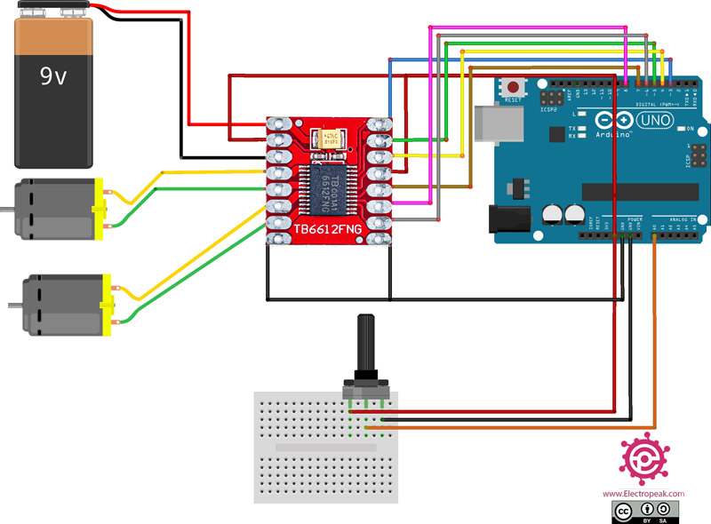
Right, I didn't include those because those aren't the problem (at least I don't see a relation myself). The part that's confusing me is that this illustration from the aforelinked guide shows 6 pins going to the arduino to control the two motors. In the code above, there are only 4 that apply to motor controls (not including the sensor/potentiometer feedback wires). How & Why is that?
I don't know how to post images directly to this forum- I don't see the options for an attachment. Anyway, you don't have to click the links I shared to see where they go, just hover over and observe that they are 1. Instructables 2. Amazon & 3. Electropeak all well known safe websites. The motor control module on amazon includes the labels on the PCB: AIN1 AIN2 PWM1 so that's 3 wires per motor input. What I don't understand is why they'd bother using more inputs than required.

The "six pins" seem to be all INPUTS to the TB6612, on the "right" side of this drawing.
PWMA from Pin3 (Arduino) for motor 1
AIN1, AIN2, BIN1, BIN2 from Pins 5, 4, 6, 8 for motor 1 and motor 2
PWMB from Pin 6 for motor 2
STBY seems to be tied HIGH/5V
GND - GND
Right... hence my confusion. Why are there 3 inputs per motor when only two are needed? This is further corroborated by that above linked diagram where they are using all 3 per motor. If only 2 are needed, then which two do I choose and how do I wire them? For motor A (for example) do I just assign the PWM pin to define speed ("leftMotorPWMPin"), and AIN1 for direction("leftMotorDirPin") and then ignore AIN2?
One for duty cycle (pwm) and two for (+/-) direction.

PWMA: PWM pin for Motor A for speed control (duty cycle)
PWMB: PWM pin for Motor B for speed control (duty cycle)
AIN1: Control signal for motor A
AIN2: Control signal for motor A
BIN1: Control signal for motor B
BIN2: Control signal for motor B
Ok. I think I get it now. So, what it comes down to is that the other motor controller they used somehow accomplishes the same level of control using just those two wires because it communicates in a different way. Is it true to say that if I continue using this motor control and if I want full directional and speed control of motors that I will always require 3 input wires per motor?
Accepting that, is it going to be difficult to rewrite the robot example code to work with this motor controller?
For the TB6612, three pins for speed plus direction+ and direction-
This information can be found on-line for every motor driver board search; "(board) datasheet"
The two-wire boards use "step" and "direction"... if you want to use a three-wire board, find a third pin for each motor and follow the fwd/rev/stop chart above for "direction"
Ok, I don't see any particular advantage to using three wires if I can get away with two. Less resources and simpler code, right? I guess I'll order some "step & direction" modules to be my goto moving forward. I did like the compact size of these examples but I'm sure I'll find a good alternative.
edit: these seem like a lovely candidate.
The L298N is not an efficient motor driver.
The "robot" page you referenced is using the DRV8833 motor driver which uses "two Arduino pins" for two DC motors (total four pins). The code uses one pin for direction (fwd/rev) and one for steps (speed/PWM). You can find them for the same price as the L298N.

This topic was automatically closed 180 days after the last reply. New replies are no longer allowed.