The sensor has been outputting a raw value of about 4000. That is to say, the transformation of the function outputs is around 1600000~400000. Not the 0 to 30 values I expected to output.(I tried to use other development board ESP32 to read the sensor value using ADC and its own power supply pin, and still output the original value of 4000, as shown in the figure below.)
Abnormal output
Normal output:
This is the output I expect, but I can't reproduce the normal output (last month was very occasionally normal output, I don't know why it can't normal output now and the environment has not changed...Analog circuits are too much like witchcraft...)
I try to do:
Measured with a digital multimeter, the power supply pin is about 3.1V~3.3V(maybe my positive and negative probes are not accurate).
Check XIAO's ADC using ADC pin to GND pin for any problems with Analog pins read GND and VCC respectively, with 12bit resolution and output of 100 and 4000 + respectively.XIAO is fine.
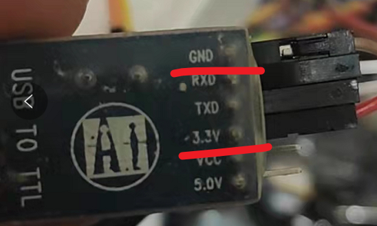
The Sensor connects the TTL to USB power supply pin, but the output is still abnormal.(I used PWM pin by esp32 or xiao MCU to output analog 3.3V, results same to abnormal output)
If the sensor signal output is connected to MCU, the high value of 4000 is output(The original value). Seems to be the power problem, someone tell me how to minimize the power ripple effect and make the 3.3V stable output provided by the battery?
But when I unplug the sensor, the MCU outputs random values, and I don't want the sensor output to be affected by other factors.
other
Asked the store, customer service said this is not normal, the sensor should output the value of 0~500, if the sensor monitors the current output of 200~400, not monitoring the general output of 0~30 range.
Maybe there's something wrong with the accuracy of the multimeter, because it costs $5 to $10. I ordered a FLUKE 17B+ online and it will arrive in a few days.
Sorry to bother you. moonshine reduction filter Can provide the link of the code? What I found on the Internet is a device for filtering wine. I don't quite understand its connection with sensors.
I don't know enough about the sensor or it's "jitter" but from experience with temperature sensors, I can suggest filling an array, and averaging the values. This specific sensor data sheet turned me off, not because it was in another language, but because it states a reference voltage of 1.5 and then a range of 0 - 3 volts, which made me wonder if it will work correctly with analogRead();.
It's probably only rated for around 25mA. I think its only intended to power a few external logic ICs if required in an external circuit. This is similar to some FTDI adapters I've used where its 3.3V is generated in the serial IC and is rated for arounf 40mA.
Solution: Use a proper 3.3V power supply.
EDIT: OK, it looks like your sensor draws only 20mA, however I see no capacitor across the sensor's VCC and GND pins or on the breadboard.