I dont post much, but when I do, its usually because I need help with something and dont want to risk ruining any of my components.
Today, I would simply like to make sure my wiring makes sense.
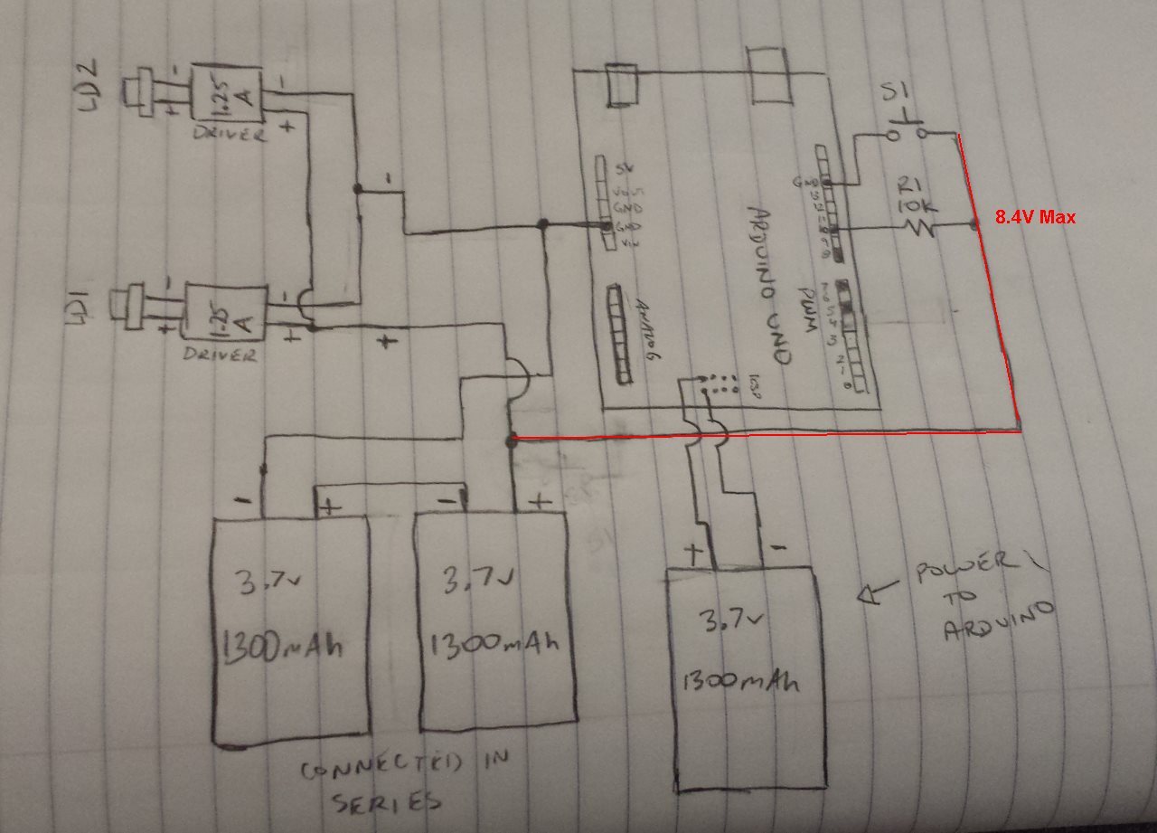
Im using two 445nm Laser Diodes, both using laser drivers and being driven at approx. 1.25A each (They are wired in parallel). They put out a little more than 1W of power each. Im using two 3.7V 1300mAh lipo batteries in series to run these. Ive hooked the lasers up in parallel with the 2 lipos in series and it works just fine, now im trying to incorporate it into the Arduino to be able to turn them on and off with a momentary pushbutton.
I am unsure of whether or not ill need a transistor. I thought that if I supplied the lasers with their own power source and drivers, the Arduino wont have to worry about limiting current.
So here is the drawing...I apologize if it may look a little messy. Ill figure out the code later, I just want to be sure that the wiring will work. Also, note that pins; 5,7, and 8 are shaded in because they are already being used to drive servos.
You connected the 8.4V to Arduino Uno input pin, the Atmega 328 will gone in no time, and if you press the pushbutton, you will short the positive and negative of the 2 lipos in series, the battery will blow up.
I'm also trying to drive a laser with the arduino pro micro.
I really don't know a lot about this kind of stuff, but I'm hoping I got the research right
Just trying to make the arduino turn the laser on and off as a flashing pattern that listens to audio.
Due to physical location of the laser (since it can't be directly driven by arduino due to its power consumption), it's only able to get a 5V and 4A power supply as an auxillary source of power (other components in parallel need that power to be from those batteries because I have no more room)
Its a 5mW 650nm Red Laser diode WITHOUT A DRIVER
It would be turned on and off with an npn transistor ( I bought both tip120 <more expensive, specs seemed to say I couldn't use much else> and 2n2222a <cheap for replication, but only one source showed me I could use it?> since my research showed they would both be good)
I'm thinking I should also use a LMS1117 Voltage regulator to drop it to 3.3 V, and a 47 ohm resistor (1/4watt) to limit current
I saw somewhere a capacitor to regulate is a good idea too, someone showed a spec using a 100nF cap which I actually have handy.
Basically I think it would look like the diagram I have attached,
Does anyone see anything wrong with this? Should I also have a resistor between the transistor and Arduino pin? If so is 100 ohm suitable?