How long does it take to upload a sketch to a breadboard Arduino ?

larryd:
Leave the breadboard cct. wired to the 7805 (with input 100nF capacitor).
Your cct. in Figure 1 will work, however, the .33 can be changed to .1uF (ceramic) mounted very close to the input of the regualtor.

those are both the same then, right ?
100 nF = 0.1 uF ?
or did you differentiate the 100nF from the ceramic one because it had to be a polarised electrolytic one ?

larryd:
Therefore the breadboard controller will be powered from the external 7805.

i don't have a polarised 100 nF cap so i just stayed with the 10 uF on both the 7805 power pins.

needless to say, it didn't fix the problem.

larryd:
This makes no sense, there must be a bad wire.

indeed - so i tried another component configuration like this;
EDIT: without the 10k on the RESET pin

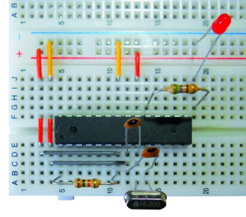
my previous setup where the wires joining the two power rails was a bit stretched, even though continuity was OK, perhaps it wasn't optimal, so i routed it along a path where it was a more than sufficient length - don't know if being higher off the breadboard (rather than flat on it) becomes a new issue...

if i ran the power wiring over the 328 chip would that be bad ?

the resistor for the LED is also bridging the 328 chip - might that be enough to cause interference ?
(it is high enough over the chip body that there's no contact, even to the casing, let alone the pins.)

i have also changed the TX/RX wires to a new set, what sort of LED flashing pattern should i be seeing during upload - i noticed the RX LED flickered briefly, but the TX one didn't light up.

should i just abort this TX/RX method and proceed to use the SPI connections ? (ie. usng ICSP instead.)

if i have to plug the Old 328 back into the UNO board to test that TX pin - i might as well just use the Old 328 as a programmer chip.

would that be a "better" option for trouble-shooting ?

100nF is .1uF

I assume the power unit going to the 7805 is filtered DC, so the input capacitor can be 100nF

"if i ran the power wiring over the 328 chip would that be bad"
No it’s okay. It’s only bad if you want to remove the chip later.

"the resistor for the LED is also bridging the 328 chip - might that be enough to cause interference ?"
It’s okay.
But I like the cct. layout in the last post :slight_smile:

The LED sequence should be the same as if the chip was plugged into the UNO.

If you use the ICSP method to upload code to the breadboard controller you will need a second controller on the UNO.
The breadboard controller will get the sketch but it’s bootloader will be erased.

Excuse me as a lot of water has gone under the bridge.
Why are you moving the controller to the breadboard to program it there when it can be more easily programmed in the socket on the UNO?

i would like to avoid pulling chips off the Uno board as it's an original and i'd like to keep it as intact as possible

I have removed the controller chip 100s of time and it keeps on ticking :wink:

larryd:
100nF is .1uF

I assume the power unit going to the 7805 is filtered DC, so the input capacitor can be 100nF

i see, okay then - both sides will have the ceramic 0.1 uF then.

larryd:
"if i ran the power wiring over the 328 chip would that be bad"
No it’s okay. It’s only bad if you want to remove the chip later.

fair point, although the wiring would be easy enough to pull aside temporarily.
i do intend to keep this "Breaduino" as a permanent setup though.
(although if i want to use it as an example of "how to make your own Arduino with "just" the 328 chip, then i really have to learn all the pitfalls that can happen.)

larryd:
"the resistor for the LED is also bridging the 328 chip - might that be enough to cause interference ?"
It’s okay.
But I like the cct. layout in the last post :slight_smile:

me too - nice and tidy, and i like bringing the power rail to one side.
the 10k for the RESET is also quite clever !

larryd:
If you use the ICSP method to upload code to the breadboard controller you will need a second controller on the UNO.

yes, i do have the Old 328 waiting to be put back in.

larryd:
The breadboard controller will get the sketch but it’s bootloader will be erased.

oh, i see - ICSP (using Arduino ISP) always erases the bootloader ?

larryd:
Excuse me as a lot of water has gone under the bridge.
Why are you moving the controller to the breadboard to program it there when it can be more easily programmed in the socket on the UNO?

because i want to have two Arduinos - i burned my Nano :frowning: and this Breaduino is supposed to be its replacement.

this upload process was all a stop-gap measure because i actually have bought a cheap CH340G USB-to-TTL serial converter to go with the Breaduino, but that kept failing - (i already have the drivers detected in Windows and loop-back test runs okay) - i have a feeling, that CH340G module is actually okay, and the problem (stk500 error) is actually related to the breadboard issue being addressed here.

you did suggest to remake the circuit on a different part of the breadboard - i probably should try that as the last resort before giving up with the TX/RX method. The breadboard row with the TX pin of the New 328 could be faulty.

larryd:
I have removed the controller chip 100s of time and it keeps on ticking :wink:

do you use some kind of tool ?

i'm still a n00b obviously, and i go really slowly prying the chip up carefully from both sides incrementally.

putting it back in is a bit more difficult, especially with a fresh chip still with splayed legs, on a breadboard, i can use a small flat plastic panel to simultaneously push the pins inwards on the one side while the pins on other side are just on the edge of the breadboard holes. On the UNO board socket this is a bit more tricky as the plastic panel is a bit harder to hold in position.

i get nervous "flattening" a fresh chip, not knowing if pressing it against the table (for eg.) might go too far.

i've even stacked a 28-pin machine socket into the UNO DIP-socket to make plugging in a 328 that little bit easier !

EDIT:
oh, i forgot to correct myself from earlier - i have the Rev.3 board, so it's NOT a FTDI chip but the Atmel 16U2.

OK - so i'm now making more progress using ICSP.

i no longer get the stk500 error !! :smiley:

i believe the RESET works ok - i have added the 10uF b/n RESET and GND on the Programmer Board, and it seems that i did NOT need the 0.1 uF cap in series with the Target RESET.

it is now an issue of finding the right signature; the error is now;

avrdude: Expected signature for ATMEGA328P is 1E 95 0F
         Double check chip, or use -F to override this check.

should i just redo burning a bootloader ?

or is this an issue of editing the boards.txt to match the "Breaduino"

what i have done already is this;

##############################################################

 // ..... this is the original settting

uno.name=Arduino Uno
uno.upload.protocol=arduino
uno.upload.maximum_size=32256
uno.upload.speed=115200
uno.bootloader.low_fuses=0xff
uno.bootloader.high_fuses=0xde
uno.bootloader.extended_fuses=0x05
uno.bootloader.path=optiboot
uno.bootloader.file=optiboot_atmega328.hex
uno.bootloader.unlock_bits=0x3F
uno.bootloader.lock_bits=0x0F
uno.build.mcu=atmega328p
uno.build.f_cpu=16000000L
uno.build.core=arduino
uno.build.variant=standard

##############################################################

 // ..... this is what i have added for the Breaduino

unoSA.name=Arduino Standalone (EFuse=0xfd)
unoSA.upload.protocol=arduino
unoSA.upload.maximum_size=32256
unoSA.upload.speed=115200
unoSA.bootloader.low_fuses=0xff
unoSA.bootloader.high_fuses=0xde
unoSA.bootloader.extended_fuses=0xfd
unoSA.bootloader.path=optiboot
unoSA.bootloader.file=optiboot_atmega328.hex
unoSA.bootloader.unlock_bits=0x3F
unoSA.bootloader.lock_bits=0x0F
unoSA.build.mcu=atmega328p
unoSA.build.f_cpu=16000000L
unoSA.build.core=arduino
unoSA.build.variant=standard

##############################################################

they key difference is the Extended Fuse - i used 0xfd because that's what it is when i used Nick Gammon's "Atmega_Board_Detector" sketch.

i do intend to keep this "Breaduino" as a permanent setup though.

With your UNO, you could use a sacrificial 28 pin machine socket with a ZIF socket soldered in.

Plug the assembly in the board socket, the ZIF socket is easily opened and closed.

With programming the Arduino with ICSP, the chip memory is erased, including the bootloader area.
'always' is another subject which I will not go into.

BTW:
Have you looked at the Arduino pro mini?

It is much like the UNO and Nano, however, has no on board programming cctry.
You do need an FTDI cable ~$7-15 (for bootloader programming) but could ICSP them also.
You get two more analog inputs compared to the UNO.
Many of us use them all the time as they are ~$3.00, they are small, have all necessary components for the controller to run.

I use a staple remover to get the chip out of the UNO socket.
Slow and sure wins the race.

Highly highly recommend you get an IC pin straightener.
I keep one of these handy and use it prior to installing the controller :

On one of my UNOs I have installed a machine socket into the original UNO socket.
This can be replaced as needed.

or is this an issue of editing the boards.txt to match the "Breaduino"

When programming the Atmega 328P-PU DIP, use: Board Arduino/Genuino UNO

If the blink sketch is working on the breadboard, the fuses should be okay.

Think all your questions have been responded to :art:

larryd:
On one of my UNOs I have installed a machine socket into the original UNO socket.
This can be replaced as needed.

yep, that's what i did too !

larryd:
Plug the assembly in the board socket, the ZIF socket is easily opened and closed.

I use a staple remover to get the chip out of the UNO socket.
Slow and sure wins the race.

Highly highly recommend you get an IC pin straightener.
I keep one of these handy and use it prior to installing the controller :

GREAT TIPS !
Thanks !! :slight_smile:
didn't realize they had tools for IC pin straightening - was inevitable i suppose, have to get me one of those for sure !

larryd:
With programming the Arduino with ICSP, the chip memory is erased, including the bootloader area.
'always' is another subject which I will not go into.

heh-heh, i understand your avoiding such definitive statements ! :smiley:

larryd:
BTW:
Have you looked at the Arduino pro mini?

It is much like the UNO and Nano, however, has no on board programming cctry.
You do need an FTDI cable ~$7-15 (for bootloader programming) but could ICSP them also.
You get two more analog inputs compared to the UNO.

it's that FTDI cable that makes it (Pro Mini) more expensive than the Nano (yes, just the first one... but i only want one... for now...)

plus the Pro Mini has a few I/O pins that aren't breadboard friendly.

larryd:
When programming the Atmega 328P-PU DIP, use: Board Arduino/Genuino UNO

i still use the IDE v1.0.5 - and choosing > Board > Arduino Uno - doesn't work :frowning:

larryd:
If the blink sketch is working on the breadboard, the fuses should be okay.

hmm.... then something else is causing the signature mismatch error.
where do i access that "-F to override this check." ?
does this entail performing DOS-style commands in some Arduino sub-directory ?

larryd:
Think all your questions have been responded to :art:

indeed - thank you so much for your patience - it really does give me comfort amid the frustration.

You only need one FTDI cable, then you buy 50 pro minis :wink:

I'm using 1.69 IDE

“where do i access that "-F to override this check." ?”
Not sure.

You might find this interesting.
Pro Mini and breadboard use:
https://forum.arduino.cc/index.php?topic=445951.msg3160567#msg3160567

There are other hardware tips in the thread that you may also find interesting. ~400 posts, get a 0xC0FFEE

larryd:
You only need one FTDI cable, then you buy 50 pro minis :wink:

haha - i only want one :smiley:

larryd:
You might find this interesting.
Pro Mini and breadboard use:
Share tips you have come across - #287 by LarryD - General Electronics - Arduino Forum

There are other hardware tips in the thread that you may also find interesting. ~400 posts, get a 0xC0FFEE

ahh yes, that thread - haven't gone through it all yet.

larryd:
“where do i access that "-F to override this check." ?”
Not sure.

well. i found it down the rabbit-hole...
Alice
Vent
Really
Deep
Under
Da
Earth...

http://www.ladyada.net/learn/avr/avrdude.html

and finally - the signature was different because it was A DIFFERENT CHIP !! d'oh !!
ATMEGA328P is 1E 95 0F
ATMEGA328 is 1E 95 14

there were a few threads on this issue.

the solution... cheat the IDE (actually avrdude, because editing the boards.txt was NOT good enough)

i found it here.

success at last :smiley:

now i have to try uploading a more complex sketch than just Blink.ino...

success at last :smiley:

Congrats!

So “there's the rub”, your chosen name is 'BabyGeezer', it should now be 'ExpertGeezer', what to do?

larryd:
Congrats!

Thanks! :slight_smile:

larryd:
So “there's the rub”, your chosen name is 'BabyGeezer', it should now be 'ExpertGeezer', what to do?

no way !
still a long way from being Expert !

the cct. must still be dodgy though, i am still failing to burn a sketch (via ICSP) 2 out of 3 times !

i "have to" monitor the verbose output on uploading and see if Send/Recv proceeds like this;

avrdude: Send: Q [51]   [20] 
avrdude: Recv: . [14] 
avrdude: Recv: . [10]

if a few lines of "Send:..." appear with no Recv. following soon after, i know a stk500 error will follow soon after.

and with the need to edit the avrdude.conf each time, it gets to be quite a hassle ! :frowning:

since the 328("dry") works IN the UNO socket, perhaps i should set it up that way, and use the 328P on the breadboard - i haven't tried that yet, but (breadboard stability permitting) it should mean hassle-free uploading - might even mean the CH340G USB-to-TTL converter will work on that....

the Baby adventures continue....