I’m unsure if this the correct category for this , if not apologies .
I was wondering , on say a UNO , how the USB - UART interface knows when to generate a reset pulse so the processor can accept an upload .
The USB connection only has D+ and D- , so no separate control line. What is in the interface chip or how does it generate this , reset pulse and why only when the USB is connected ?
I’m using the MCP221a which can’t generate a DTR signal , but how do other interfaces achieve it ?? - is it just detecting the presence of the 5v line for example ??
I guess the question that goes with this is how does the Arduino know , after a reset , that it is receiving code for uploading its just data ( file header ??)
I'll share a link to this nice explanation of the auto-reset system on the UNO R3 (which is also used by the Mega 2560, and a similar system is on the classic Nano and various other AVR-based boards):
It is perhaps a bit tangential since it focuses mainly on the reset circuit rather than the software/protocol aspect of the serial port control signal mechanism, but it is at least closely related to your question and so might be of interest to you, or to others who find this topic while searching for information about the system.
There seem to be at least a couple of errors in that article. If we were to follow that diagram, cutting the blob would have no effect since it is bypassed with another trace. I guess we can imagine that the line below and parallel to the blob pads is not there.... To be fair, the author did comment on the quality of the diagram. Of course, the description of the purpose of the blob is correct - its purpose, where present, is to provide a convenient means to make or sever the connection at that point. I could be cut with a knife as described, or the solder simply cleared or re-applied.
In the description it says that 'we pulse the 'Pin1 on the 328P to issue the reset'. I did wonder whether there might have been a mix up with pin 1 on the 16u2, but that pin is connected to the crystal so not the case. Its probably stating the obvious, but in any event its the RESET pin on the 328P that gets pulsed to effect the reset, not the pin over which serial communications are sent. A short burst is all it takes to reset the MCU and run the bootloader.
They don't say anything about cutting a "blob". You cut the trace. A blob is used to bridge the jumper if you want to later enable the circuit once more.
I think part of the problem is that Arduino chose to symbolize the solder jumper in a confusing manner:
but Arduino instead used the symbol that is used for a normally open jumper, then added a separate connection to the schematic to indicate that it is closed.
But then the author of the article did indeed introduce an error by adding a red line through the jumper in the snippet they created from Arduino's schematic:
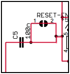
If for some reason, you wanted to disable the autoreset function, you would run a very sharp knife down between the two halves of the solder jumper at “RESET EN”, to cut the trace.
In the context of the original schematic they are referring to cutting this trace on the UNO R3's PCB:
Ok so it’s the opening of the serial link causes the reset - is there something else in say the file header so the processor then knows it is to be either uploading code or just received a message from say , the serial monitor .
No. On a UNO, if a bootloader is present, then when the MCU restarts after a reset, the bootloader will run first. The bootloader waits for a specified time for an upload to begin. If an upload starts, then the code is uploaded to flash. Once upload of the code is complete, the MCU proceeds to run the uploaded sketch.
If there is no upload started within the specified time, the bootloader exits and the MCU then runs the sketch. Once the sketch is running, the behavior of anything sent or received from Serial Monitor depends on what the sketch is programmed to do.
If no bootloader is present then on restart, the MCU just runs the sketch.
With the bootloader present, there will always be a delay of a second or so when a connection is opened to the serial port before the port becomes active. On the other hand, if the sketch has been uploaded via the SPI header (e.g. using another Adruino as an ISP programmer, or a USBASP programmer) the bootloader will be overwritten and since a reset will just restart the sketch, the delay will be considerably minimized. However without a bootloader, it will not be possible to program the board via serial. However, this functionality can be easily restored by "burning" (re-uploading) the bootloader.
Not sure exactly what happens but this is reasonable:
Code is compiled, code is ready for uploading, USB port software tells the Arduino USB chip (or external FTDI) to generate the DTR signal, DTR goes LOW . . . Arduino is Reset and Boot-loader does its thing.
Not what you are asking for, but it is possible to configure whether or not the Arduino IDE Serial Monitor will assert the control signals that trigger the auto-reset circuit:
This is configured via the board definition in the boards.txt platform configuration file, so the configuration is made at a per-board granularity, meaning it controls the Serial Monitor behavior when that specific board is selected from the Tools > Board menu.