I want to generate pulses in the (10^-6) micro-sec. range. At the moment I'm running the ATmega328p (UNO/Rev.3) 8 bits timer at a clock of 16MHz (no divison used). To get some more resolution I need more clock speed.
Is that possible with the Arduino Due? The datasheet says that the core is running on 84MHz (max.), however the cristals mounted on the Arduino Due board are much lower 32.768kHz and 12 MHz ...? This is lower than for the UNO.
You could use an ATTiny861 (or ATTIny85). They run at 16MHz from a crystal but then have an internal 4xPLL which allows one of their timer modules to run at 64MHz. That would give you 4x the resolution of the ATMega328 without having to rewrite your code too much.
What code are you using to generate the pulse? digitalWrite() is inefficient. Search for fast digital io examples. The Due is fast enough if used properly, even the UNO can generate a digital switch in 125 nanosec.
MarkT:
Modern high speed processors derive their internal clocks from a crystal oscillator
and a PLL, here the 12MHz crystal is multiplied by 7.
Thank ypu for the information. I have read (parts of) the datasheet of the SAM3X8E (uC of the Arduino Due), however it is unclear to me whether this high speed clock input can be used for Timer Counters (TC's).
the arduino analogWrite pwm uses 490hz freq,or about 2ms period.
If you want to do 1us period on the UNO, you must access the timer registers directly.
first, use a smaller divider, like 8, which gives you 0.125us per timer count,
this gives you 8 counts to get your period of 1 us.
if you use mode 11, phase correct PWM mode, all you need to do is set OCR register to 4, then you will get your 1us pulse at 50% duty cycle. the divider and mode are set in timer registers TCCRnA and TCCRnB
If you want a duty cycle other than 50%, then you must use mode 10, use ICR register to set your top (value 4), then the OCR register to control your duty cycle.
everything you need to know is in the timer/counter chapter in the atmega datasheet.
Hello Tom, thanks for your answer. This is where I'm looking for. Is there an (Arduino or other standard) board that use the ATTinny that you mentioned above? I cannot find it at the Arduino website. Rewriting the code is (probably;-) faster than designing a new AVR-PCB-board myself.
There isn't, but there is software support for it. This core supports the ATTiny861 among others
The Attiny's are very simple to use, all you need is a 16MHz crystal, 2 caps and the ATTiny861 chip. A pullup resistor on the reset pin is also a good idea. Its breadboard friendly and you can use another Arduino board as a programmer (ArduinoISP sketch).
I have attached a circuit diagram for a basic setup. This should be very easy to build up on a small piece of veroboard or protoboard. You could even build it on a proto-shield for an Arduino which would allow you to directly connect the programming pins to the Arduino shield pins.
The MISO pin, along with PB3 are also your two high speed PWM output pins which can run up to 64MHz and are generated by a 16bit timer. MOSI and SCLK pins can also be used to output the same PWM signals but inverted.
MOSI, MISO, SCLK and RESET are your programming pins which simply connect to another Arduino board when you need to program.
doughboy:
You you want a really high frequency, you can make the arduino timer use an external clock instead of the arduino 16mhz clock.
That wont work at all. The external clock input pins for the timers must be run at F_CPU/2 or slower which means the maximum you could have is 8MHz on one of the external timer input pins.
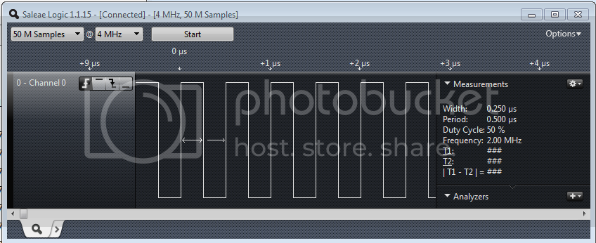
thanks for the correction. it seems the purpose of using external clock is for counting external events, not for waveform generation. So the highest freq waveform you can get out of arduino is 2.666mhz pulse. I think the OP only asks for 1us pulse, so using the sample program I provided (which give 0.5us pulse) is more than sufficient, no need to make this more complicated with external circuits.