Hi everyone,
Sorry if it's in the wrong forum, but "General Electronics" seemed the most appropriate.
I've did some tests a couple of years ago to create an electronic drum and the most obvious choice for getting a pressure sensitivity pad was to use a piezo transducer, that is in fact what is used on professional e-drum kits. I recently bought a MIDI controller that has some rubber pads, suited for finger drumming (also velocity sensitive). I opened my controller to take a look on how they achieved the sensitivity, just out of curiosity, expecting to see some sort of piezos, but is actually something very different.
The pads:

Here is the pad at the PCB level:

And on top of the PCB (between the PCB and the rubber pads), there is sheet sheet of plastic with some sort of black rough "ink" that makes contact with the traces on the PCB:
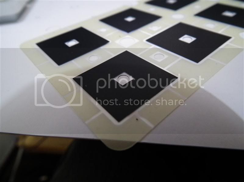
Does any one knows how this pressure/velocity sensitive system works?
Thanks in advance,
Fergo