Hi, I have a code that uses 1.1Vref (because the system is powered by battery) (ATTINY44A IC). I have connected one sensor to it and now i would like to read value of the sensor. Please check the code below.
This code uses internal reference voltage and outputs unchanged voltage rating.(THE code is for arduino and with little changes it will work for attiny)
void loop() {
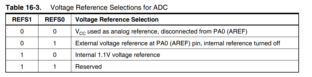
//REFS1 AND REFS0 to 1 1 -> internal 1.1V refference
ADMUX |= B11000000;
//We read A1 (MUX0)
ADMUX |= B00000001;
// Start AD conversion
ADCSRA |= B11000000;
// Detect end-of-conversion
while (bit_is_set(ADCSRA,ADSC));
float val = ADCL | (ADCH << 8);
val = val * 5.7;
Serial.println(val);
}
from my perspective, in order to read sensor value the code should be:
int sensorVoltage = analogRead (A0);
  val = (val * 5.7);
  val = (val/1024);
  val = (val*sensorVoltage);
  if (voltage<=2000){ //3V
   DO SOMETHING
  }
Unfortunately, the above code does not work as needed.
for example, if the sensor at 3v reads 2000 then it should be something like if (sensorvalue<=2000){do something};
But what if with some other battery little less or little more charged, the sensor does not read 2000 or reads some value greater than 2000 at 3v then what is the solution to it?
The value changes with battery voltage.
The code works alright with arduino but when i transfer it to attiny it does not work properly for instance, arduino reads 2000 at 3v whereas, attiny does not read 2000 at 3-3.4V.
okay, thank you Mr jim-p.
The issue now is the code works ok with arduino, i can set any range but when it comes to attiny, that exact same range does not work. What might be the issue? is the code wrong or what?
#include <avr/io.h>
float val;
float voltage;
int led = 3;
#define solar 2
void setup(){
Serial.begin(9600);
pinMode (2, INPUT);
pinMode (0b00000001, INPUT);
pinMode (led, OUTPUT);
}
void loop() {
 ADMUX |= B10000000;   // internal 1.1V refference
  //We read A1 (MUX0)
  ADMUX = 0b00000001;   //PA1
  // Start AD conversion
  ADCSRA |= (1<<ADSC);
  // Detect end-of-conversion
  while (bit_is_set(ADCSRA,ADSC));
 val = ADCL | (ADCH << 8);
//long result = ADCL | (ADCH << 8);
//val = result;
int sensorVoltage = analogRead (2);
val = (val * 5.7);
val = (val/1024);
val = (val*sensorVoltage); //Multiply by the inverse of the divider
Serial.println("val: ");
Serial.println(val);
if (voltage<=2000){ //3V
digitalWrite (led, HIGH);
}
else if (voltage>=2000){ //216
digitalWrite (led, LOW);
}
}
ok, so do i need to add voltage divider at sensor end or what? but i am confused my multimeter is showing above 3.7v for sensor.
I want it to act like if voltage is above 3.5V then do something else do something else but the range is not same as or let's say even close to that, i believe. for reference i have added an led so, if the voltage reads equal to == or below 2000 read high led and if the reading goes above the range then turn it OFF.
if the value can't be higher than 1.1v then how come the sensor reads around 6v as 2500 (serial monitor reading) but the moment i shift the codes to attiny, systems does not work as needed.
no basically it will be charging my battery. I know i have not made connection of solar to battery but that's a later stage. Currently my focus is on this sensor, it should read specific value and act accordingly
First, you will damage your 44 if you hook it up that way, so disconnect everything and hope that the 44 is OK.
Is it your intent to read the voltage of the solar panel?