Please tell me how to power the relay by Arduino board. Earlier I was giving 5V from arduino to common of the relay. But according to your connection we will connect the common to ground. Then where should we connect the 5V or 3.3V.
What coil voltage is your relay?
You might not need to connect the 3.3V.
I needed it because my relays are 3V.
I had to connect it to power the circuit on the MKR Relay Protoshield.
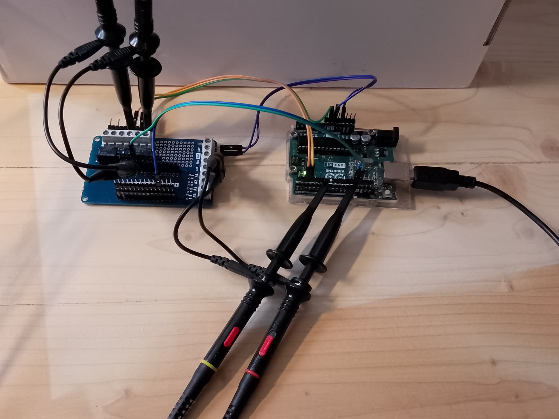
Here is how I had things connected:
To aid connection I use this type of strip of pins:
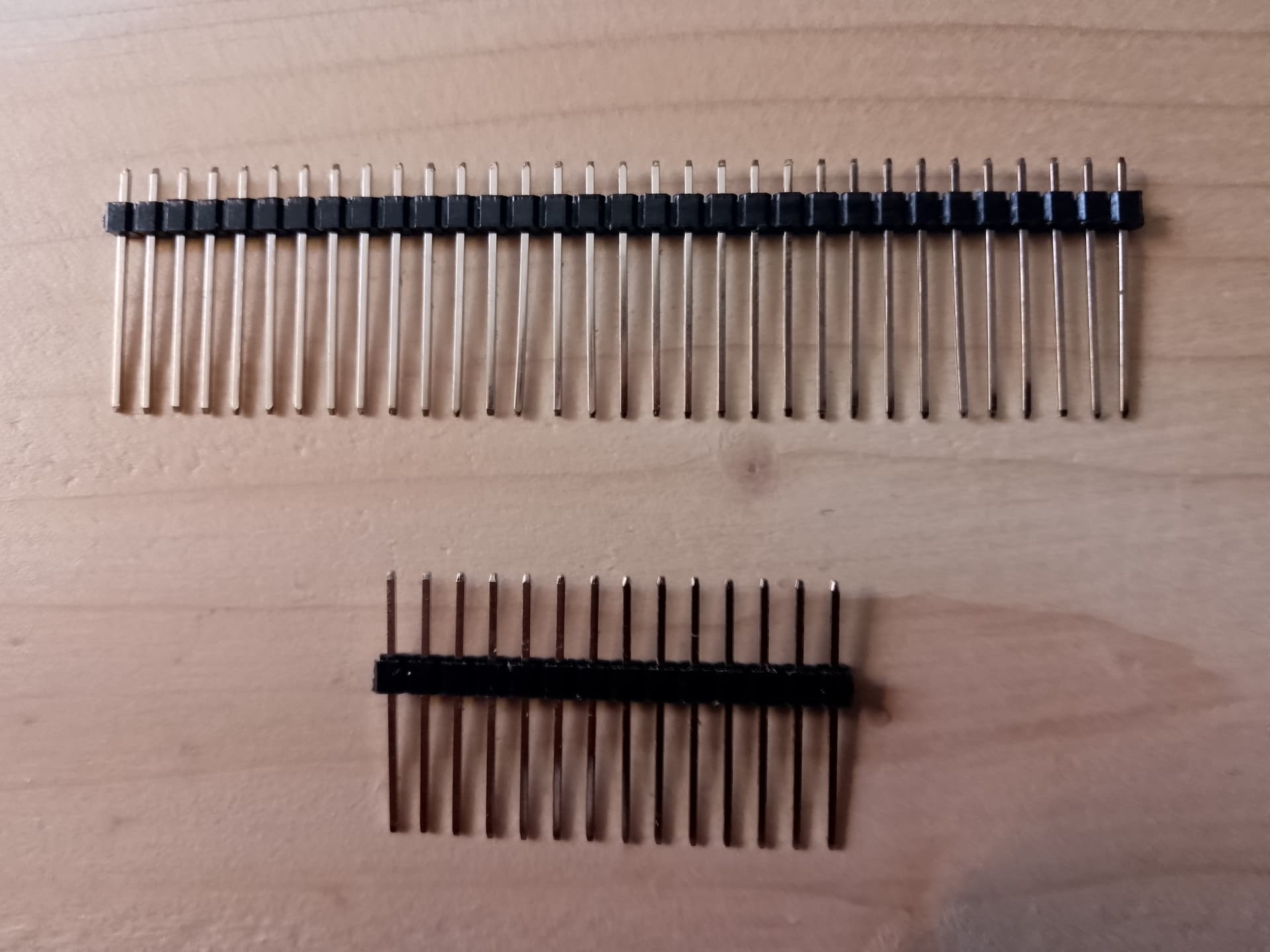
They are supplied like the upper row, but I push the pins through to make them like the bottom row.
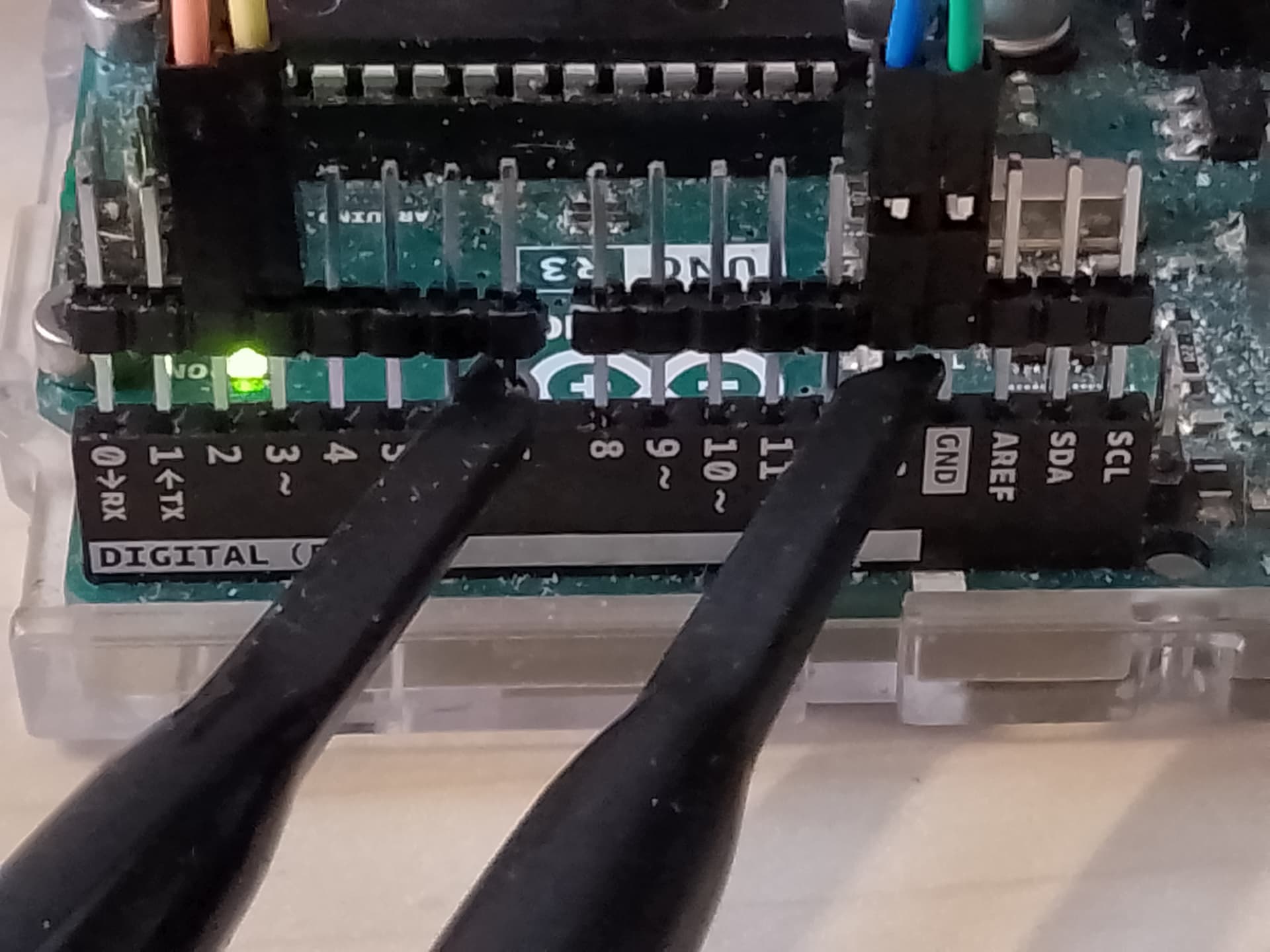
When the longer end of the pins are inserted into the connectors on the Arduino, you can plug a Du-Pont type connector above the black insulator, and clip an oscilloscope probe lower down between the insulator and Arduino.
I have used the same type of strip of pins, with every second pin removed to connect to the screw terminals.
My relay coil voltage is 24V and I have set 24V in the power supply.
Then you have no need for the 3.3V.
But you will need a MOSFET or BJT to switch the relay, and a reverse biased diode across the relay coil.
Mine is already on the Arduino MKR Proto Shield:

My Arduino pin 13 connects to the CMD2 pin that goes to R4, to switch T1-2 and RELAY2.
From the hardware it is difficult to understand. Can you please provide the connection diagram.
When the relay coil is energized, it makes a magnetic field that will change as the mechanical relay is moved. A linear Hall sensor can sense that a few times per millisecond without touching the relay at all.
This topic was automatically closed 180 days after the last reply. New replies are no longer allowed.