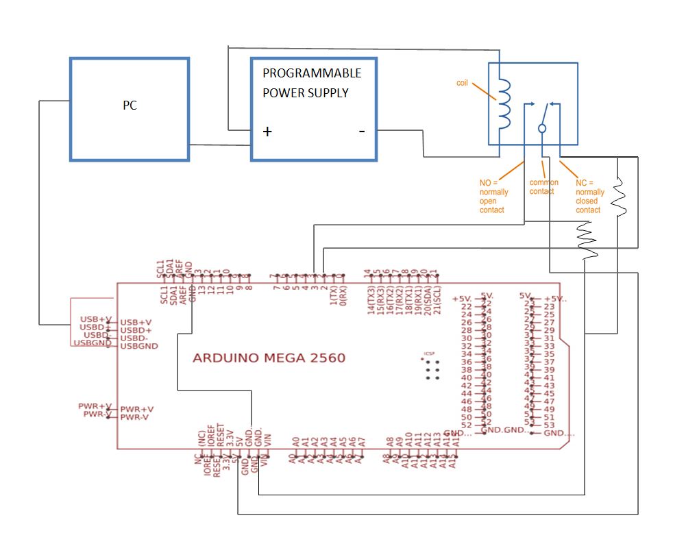
I have connected 5V of arduino board to common of the relay and NO and NC pin of relay are connected to two digital pins. Also NO and NC are pull down using 10K ohm resistor. I have to calculate the operating time. I am getting some deviated result with my code. Help me with the code.
It is always the contact that is closing that bounces.
When the relay is energised the NO contact bounces.
When the relay is de-energised it is the NC contact that bounces.
Here are some oscilloscope traces showing relay contacts bouncing.
What board are you using? If your board has an 8 or 16-bit uc then you will need to disable interrupts when reading startTime and endTime during loop if you are using interrupts
Do you really need uS resolution for the timing? If mS resolution is good enough then don't use interrupts and just poll the inputs.
As stated before you need to account for the debounce on the relay closure.
Both the contacts that open and the contacts that close when the relay switches states can bounce. Debouncing algorithms are often symmetric, treating both edges at once with a time constant large enough for the worst case, which will be the contacts that are closing.
here's code to simulate what i believe you are trying to do.
it assumes the NO and NC contacts are connected to pins 2 & 3 configured with internal pull-up resistors enabled, INPUT_PULLUP and the COMMON is connected to ground. a closed contact pulls the pin LOW
it uses pin 13 as an output to control the relay by providing voltage to the relay coil. i would use it to drive a transistor (with series resistor between the pin and base) to pull one side of the relay coil to ground with the other side connected to a power supply. (i don't know the response time fo a programmable power supply
loop() alternately calls close() and open(). they either energize or de-energize the relay coil and then wait for the relay contacts to change state. the NC contact is normally closed, so after energizing the coil in close(), it waits for the NC contact to open by going HIGH and the the NO contact to close by going LOW
results are printed by report() which output the captured times and deltas
i tested with pins on a multi-function board. change #define MyHW to #undef MyHW to used your hardware and pin assignments
output
        0     4419        0        0     4419  open
      572      572     4920     5492     5492  open
      303      319     5993     6296     6312  open
      159      159     6813     6972     6972  open
      182      184     7473     7655     7657  open
      205      205     8158     8363     8363  open
       33       34     8863     8896     8897  open
        0      203     9399     9399     9602  open
      242      242    10102    10344    10344  open
      152      152    10845    10997    10997  open
       80       80    11498    11578    11578  open
        0        0    12079    12079    12079  open
      742      742    12580    13322    13322  open
       60       60    13822    13882    13882  open
      357      357    14383    14740    14740  open
      491      491    15241    15732    15732  open
      473      486    16233    16706    16719  open
        2        2    17220    17222    17222  open
#define MyHW
#ifdef MyHW
# define time millis

const int PinNC    = A1;
const int PinNO    = A2;
const int PinCoil  = 13;

enum { CoilOff = HIGH, CoilOn = LOW };

#else
# define time micros

const int PinNC    = 2;
const int PinNO    = 3;
const int PinCoil  = 13;

enum { CoilOff = LOW, CoilOn = HIGH };
#endif

unsigned long t0;
unsigned long t1;
unsigned long t2;

char s [90];

// -----------------------------------------------------------------------------
void
close ()
{
    digitalWrite (PinCoil, CoilOn);
    t0 = time ();

    while (LOW == digitalRead (PinNC))  // wait for NC contacts to open
        ;
    t1 = time ();

    while (HIGH == digitalRead (PinNO)) // wait for NO contracts to close
        ;
    t2 = time ();
}

// -----------------------------------------------------------------------------
void
open ()
{
    digitalWrite (PinCoil, CoilOff);
    t0 = time ();

    while (LOW == digitalRead (PinNO))  // wait for NO contacts to open
        ;
    t1 = time ();

    while (HIGH == digitalRead (PinNC)) // wait for NC contracts to close
        ;
    t2 = time ();
}

// -----------------------------------------------------------------------------
void report ()
{
    unsigned long dT1 = t1 - t0;
    unsigned long dT2 = t2 - t0;
    sprintf (s, " %8lu %8lu %8lu %8lu %8lu  open", dT1, dT2, t0, t1, t2);
    Serial.println (s);
}

// -----------------------------------------------------------------------------
void loop ()
{
    close ();
    report ();
    delay (500);

    open ();
    report ();
    delay (500);
}

// -----------------------------------------------------------------------------
void setup ()
{
    Serial.begin (9600);

    pinMode (PinNC,   INPUT_PULLUP);
    pinMode (PinNO,   INPUT_PULLUP);
    pinMode (PinCoil, OUTPUT);
}
i'm guessing that you expect the PC to control the relay.
from the code it looks like you expect to make a measurement from when the NC contact opens and goes LOW to when the NO contact closes and goes HIGH.
i assumed you want to measure the time from when the coil is energized. that requires that the Arduino control it and that is the purpose of pin 13.
i wired things so that i could test the code on my hardware. if you understand what i've done, you should be able to modify your code to better suit your approach
I did a test to see how well the results obtained from gcjr's code agreed with the results obtained from an oscilloscope.
I modified gcrj's code slightly, so that it would wait until I gave it a trigger signal before it switched the relay on or off. This was done to give me time to save the results before the next switching event.
The oscilloscope traces show:
Channel 1 - yellow trace - trigger signal
Channel 2 - red trace - relay power
Channel 3 - blue trace - NC contacts
Channel 4 - green trace - NO contacts
There are automatic measurements of the times being measured
The Arduino results on the serial monitor are shown on the same screenshot.
The last result on the serial monitor is the same run that the oscilloscope trace shows.
The results obtained from the Arduino are very close to the results from the oscilloscope. There is a maximum difference of 3µs between the Arduino and oscilloscope in the results shown.
Both the Arduino and the oscilloscope measure the time to the beginning of the contact bounce. The bounce time is extra.
The code that I used was a modified version of the code that gcjr posted in post #11.
I added a wait() function that halted the program until a trigger pulse was received.
I also commented out the first line of the code to select the hardware in use.
//#define MyHW
#ifdef MyHW
#define time millis

const int PinNC    = A1;
const int PinNO    = A2;
const int PinCoil  = 13;

enum { CoilOff = HIGH, CoilOn = LOW };

#else
#define time micros

const int PinNC    = 2;
const int PinNO    = 3;
const int PinCoil  = 13;
const int waitPin  = 7;

enum { CoilOff = LOW, CoilOn = HIGH };
#endif

unsigned long t0;
unsigned long t1;
unsigned long t2;

char s [90];

// -----------------------------------------------------------------------------
void
close ()
{
  digitalWrite (PinCoil, CoilOn);
  t0 = time ();

  while (LOW == digitalRead (PinNC))  // wait for NC contacts to open
    ;
  t1 = time ();

  while (HIGH == digitalRead (PinNO)) // wait for NO contracts to close
    ;
  t2 = time ();
}

// -----------------------------------------------------------------------------
void
open ()
{
  digitalWrite (PinCoil, CoilOff);
  t0 = time ();

  while (LOW == digitalRead (PinNO))  // wait for NO contacts to open
    ;
  t1 = time ();

  while (HIGH == digitalRead (PinNC)) // wait for NC contracts to close
    ;
  t2 = time ();
}

// -----------------------------------------------------------------------------
void report ()
{
  unsigned long dT1 = t1 - t0;
  unsigned long dT2 = t2 - t0;
  sprintf (s, " %8lu %8lu %8lu %8lu %8lu  open", dT1, dT2, t0, t1, t2);
  Serial.println (s);
}

// -----------------------------------------------------------------------------
void wait ()
{
  while (LOW == digitalRead (waitPin))  // wait for trigger signal
    ;
}

// -----------------------------------------------------------------------------
void loop ()
{
  wait ();
  close ();
  report ();
  delay (500);

  wait ();
  open ();
  report ();
  delay (500);
}

// -----------------------------------------------------------------------------
void setup ()
{
  Serial.begin (9600);

  pinMode (PinNC,   INPUT_PULLUP);
  pinMode (PinNO,   INPUT_PULLUP);
  pinMode (waitPin, INPUT);

  pinMode (PinCoil, OUTPUT);
}
The relay that I used was one of the ones on a Arduino MKR Relay Proto Shield, as that was the only one available.
This shield has N channel MOSFETs to switch the relays. Schematic here.
I powered the shield from the 3.3V pin of an Arduino Uno R3.
I used pin 13 of the Uno to switch one of the relays on the shield.
The NC relay contact went to Uno pin 2.
The NO relay contact went to Uno pin 3.
The COM relay connection went to Uno GND.
I also used a function generator, manually triggered to provide a 5V trigger pulse to Uno pin 7.
You will have to adapt the arrangement to suit your own hardware.
You could use a push button to generate the trigger pulse.
But, I have a normal D Relay, which have NO, NC and common. Where should I connect the 3.3V i.e. how will I power the relay through Arduino? Also how have you connected the pin 13, please share the photo of connection if possible.