I'm trying to make a boost driver to power a string of 6 x 1w LEDs from a 12 volt supply. Analogue electronics is not really my thing. Yet. Gotta start somewhere, though:
Farnell has around a gazillion different flavours of 68uH inductors, but as I only half understand what's going on in the circuit, I'm not sure which characteristics are critical. I've narrowed the list down to SMD ones that look like they can handle the current, but I'm stuck on the following:
Resonance - in this sort of simple booster design, do I want an inductor that self-resonates at the driver's switching frequency (1.2MHz) or is that a bad thing? (ie should I choose one that's resonant frequency is nowhere near 1.2MHz or its harmonics)?
I understand Q factor from mixing desks - it's the width of the bell curve around the central frequency - but is it critical in this sort of design? Do I want a large one or a small one?
Core losses - the datasheet says "the inductor should have low core losses at 1.2MHz and low DCR". I've narrowed the range of inductors down to ones with low resistances, but I'm not sure how to interpret the low core losses bit. I'd imagine it's to do with the core material, but there are many options, from air through to a variety of metals. Do I want something more ferrous or less ferrous?
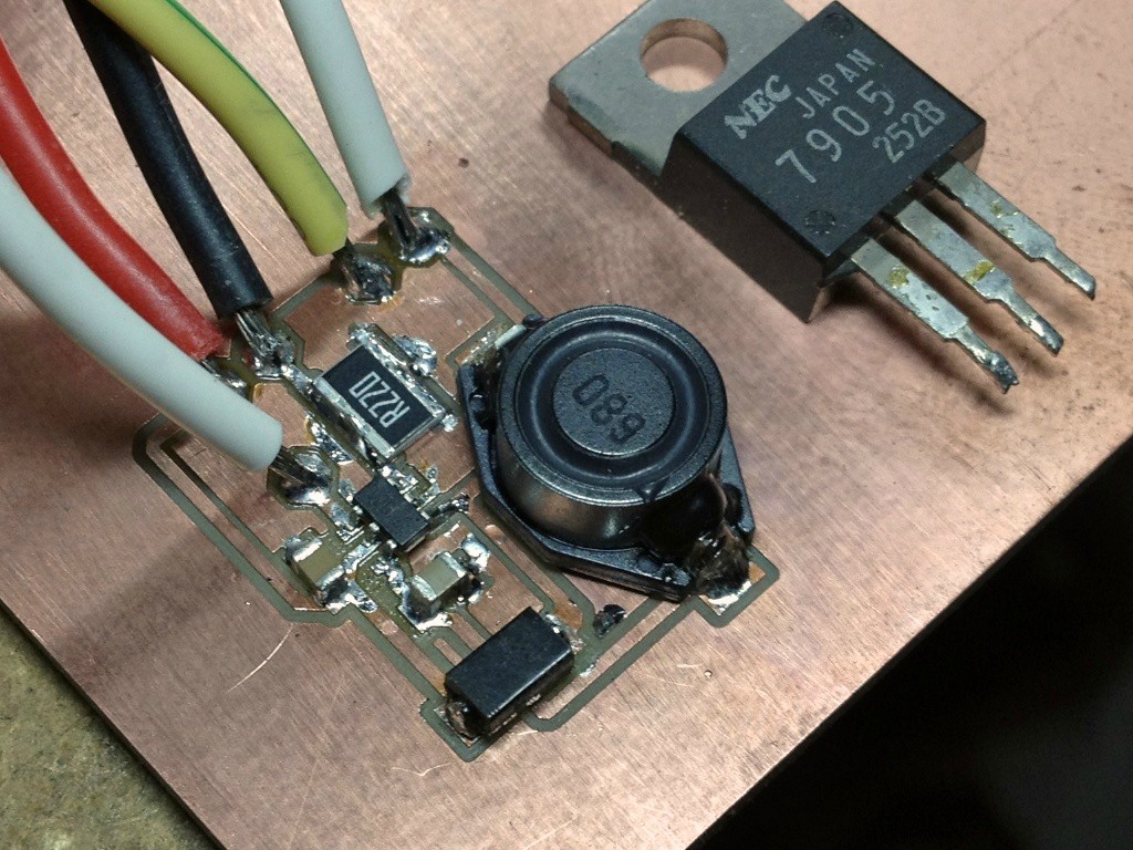
(incidentally, I'm planning on cutting a PCB for this on my mill, rather than trying to breadboard it - I understand the need to keep leads as short as possible, and this will be running from a car battery so start-up current should be accommodated OK)
I haven't done a lot of power supply designs. However, as a general rule I'd think you want to minimize the DC resistance (DCR) as much as practical, this in turn will help minimize the power lost during the voltage conversion.
The important characteristics of the inductor are:
Self-resonant frequency higher than the switching frequency - ideally 10x or more higher (but you may have to settle for 5x). I don't see any mention of resonant frequency for that inductor. The inductance plot goes up to 1MHz but shows a slight rise in inductance at that frequency, which may be due to approaching resonance.
Saturation current higher than the peak switched current. The inductor you chose saturates at 1.2A and the LEDs run at 350mA, so you have plenty of margin.
DC resistance low enough not to dissipate too much power. That inductor is 0.73 ohm maximum so OK @ 350mA.
Core losses low enough at the switching frequency. The plot for that inductor goes up to 1MHz so core losses are presumably low at that frequency.
I think you will find that inductor OK for this application.
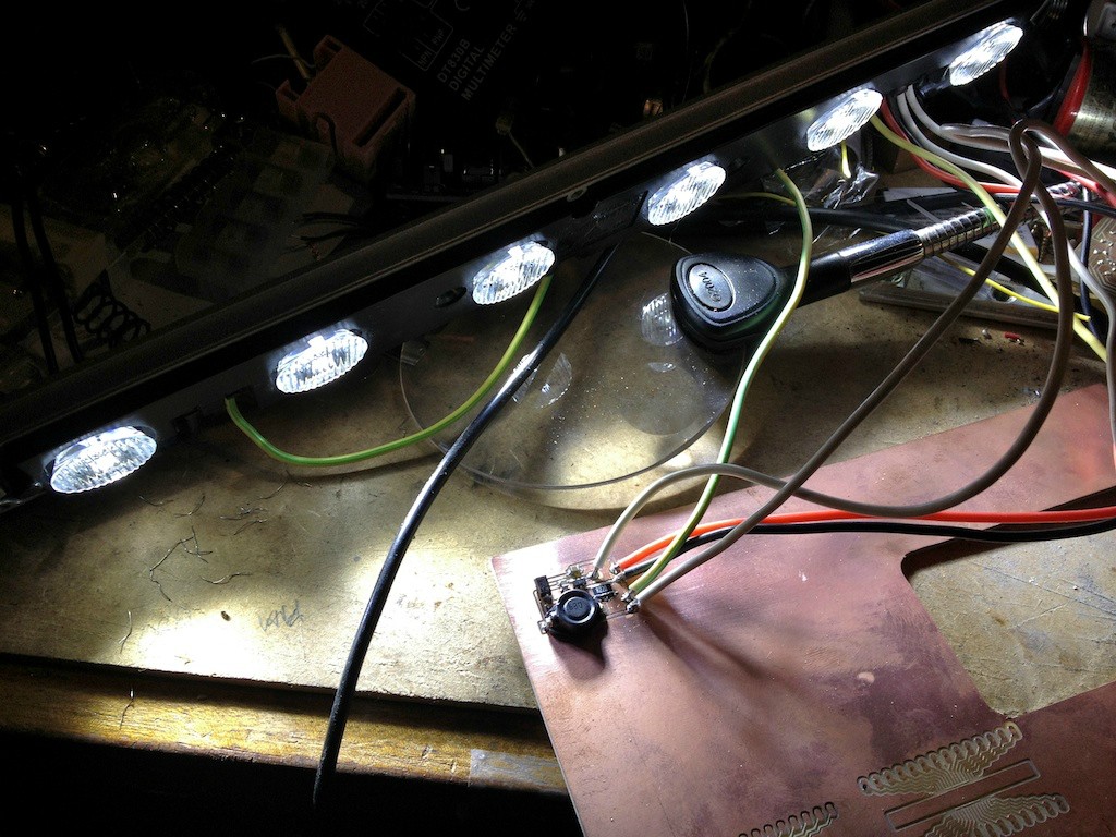
Good to know I'm on the right path. I've got plenty of these 6 x 1W LED strips so at least it won't be the end of the world if I blow one up.
Once I get one working, I might order a range of cheaper inductors with different characteristics so I can see what effect they have on the circuit... see how low I can push the total cost / board size before things start to overheat
For switch-mode supplies ferrite cores are almost universal, since they have good power handling. For RF signal transformers iron-dust cores are very common - I think they can have higher Q-values (lower loss) and much less temp-dependence. There are many many formulations of inductor core materials and its a complex business selecting an inductor - many factors are involved, Q, linearity, temp dependence, frequency range, power handling.
For fixed value inductors gapped cores are usually used - the inductance is controlled more by the geometry than the ferrite and linearity and current-handling is improved compared to a complete magnetic circuit. For (non-resonant) transformers ungapped cores are generally used to increase transformer efficiency.
The Best method I've ever found was to find a reference design from the Mfr and use it... They've already done the real work and the reference design is there to sell the part.
I designed and built several switcher based buck and boost topology power supplies for production and I found that copying the reference design as closely as possible was the best bet.
DC42's advice was spot on from every aspect.
Re. using manufacturer's reference design - yup, at my level of expertise it's my best hope of getting anything working
I got bored of looking through the hundreds of boost converters that all seem to do the same thing but need subtly different support components round them, so I just looked for the cheapest one and thought I'd jump in. I'm sticking to the example circuit given in the datasheet, but it didn't specify part numbers for the external components, hence my questions.
Kinda glad, too - if they'd given me a precise shopping list I'd have learnt little more than you do from putting a lego model together. As it is I've learnt about SMPS theory and inductors, and much of it from the kind responses here.
I know you shouldn't get too overconfident after one success, but it's making me think about using buck/boost circuits elsewhere. Most of our house runs on solar power / car batteries / 12v, so it kills me to have to use linear regulators to drive all my little Arduino projects; burning off 7 of my 12 volts as heat in everything I make. I suppose they're hard to beat for cost and convenience.