I was thinking about this too. But me personal I have zero knowledge about the Raspberry Pi pico rp2040 PIO
programmable Input Output. I did some googling about it. But I didn't find yet a really good tutorial about it. @westfw do you know a tutorial or a library that has things like
super-high-speed PIO-based
I am not sure you have read the responses carefully.
Just NOP instruction takes 62.5ns (F_CPU = 16MHz, 1s/16 000 000 = 62.5ns for 1 cycle). NOP is 1 cycle instruction. There is no time for the loop.
This:
On ATmega328P the CBI, SBI instructions take 2 cycles each. NOP takes 1 cycle. Without NOP instruction it would be approximately 125ns pulse (if we suppose the pulse edge somewhere in the middle of the instruction). This is the minimum like @westfw wrote above.
delay(8);       // 8ms
delayMicroseconds(799); // 0.799mstype or paste code here
8.799ms after the input pulse goes low is not the right place to start the pulse if we are wanting to start 200ns before the 9ms is over. (i know we can't do 200ns exactly).
There are a million nanoseconds in a millisecond, not a thousand.
The correct figure is going to be closer to 8.999ms.
@JohnLincoln
I think, delayMicroseconds(0) takes 4 cycles so it would be 250ns.
50ns per cycle is with 20MHz which is perfectly good with 328P. Years ago I made an experiments with various frequencies, mainly with 1284P but also 328P. ATmega works perfectly up to 25MHz.
I think delayMicroseconds takes MORE that 4 cycles, and the timer used only has a resolution of 4us, so it's not very useful for delays less than 4us...
EDIT:
Routine call may vary from 2 to 7 cycles in dependence of type call which depends on program size too.
RJMP - 2 cycles,
JMP - 3
RCALL - 5 or 7
Here is what I noted for myself years ago.
Function call: 2 + 3 cycles for constant parameter (2xLDI + RCALL)
4 + 3 cycles for variable parameter (2xLDS + RCALL).
If the program is small or simply near of the function can use RJMP (only 2 cycles)
instead of RCALL.
yes, it does
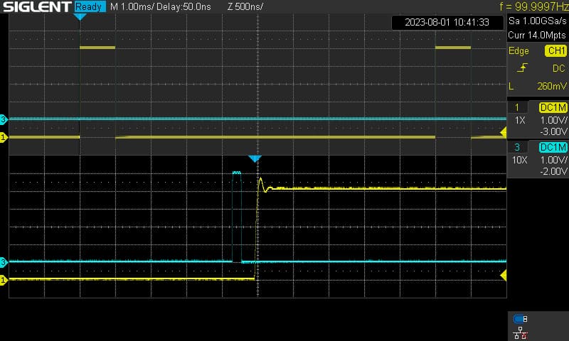
If I put the noInterrupts() before the delay(8), then the pulse is generated just a few microseconds after the falling edge of the chopper signal.
delayMicroseconds() doesn't need interrupts, delay() does.
If it supposed to be periodic signal it have to run with interrupts disabled so no delay().
Some time ago I played with R-R2 ladder. Here is a sine signal sample:
// Define the registers and bit masks for manipulating pin 13 (PB5)
#define LED_PORT    PORTB
#define LED_DDR     DDRB
#define LED_BIT     5

// Function to set the LED pin high
void inline ledOn() {
  LED_PORT |= (1 << LED_BIT);
}
// Function to set the LED pin low
void inline ledOff() {
  LED_PORT &= ~(1 << LED_BIT);
}
// Function to initialize the LED pin as output
void inline setupLed() {
  LED_DDR |= (1 << LED_BIT);
}

volatile bool chopperFallingEdgeDetected = false;

void setup() {
  setupLed();
  pinMode(2, INPUT_PULLUP);   // Chopper pin with internal pull-up resistor enabled

  // Attach interrupt to chopper pin (INT0) for detecting falling edges
  attachInterrupt(digitalPinToInterrupt(2), handleChopperFallingEdge, FALLING);
}

void loop() {
  if (chopperFallingEdgeDetected) {
    // Clear the interrupt flag
    detachInterrupt(digitalPinToInterrupt(2));
    noInterrupts(); // 1 cycle

    delayMicroseconds(8991); // 8.991ms
    asm volatile("NOP");
    asm volatile("NOP");
    asm volatile("NOP");
    asm volatile("NOP");
    asm volatile("NOP");
    asm volatile("NOP");
    asm volatile("NOP");
    asm volatile("NOP");
    asm volatile("NOP");

    // Turn on the LED (High time: 100 ns)
    ledOn(); // 2 cycles
    ledOff(); // 2 cycles, turn off immediately for cca 125ns
    interrupts(); // 1 cycle
    //     no any delay
    // Re-attach interrupt to chopper pin (INT0) for detecting next falling edges
    attachInterrupt(digitalPinToInterrupt(2), handleChopperFallingEdge, FALLING);
    // ...

    chopperFallingEdgeDetected = false;
  }
}

// ISR to handle chopper falling edge
void handleChopperFallingEdge() {
  chopperFallingEdgeDetected = true;
}
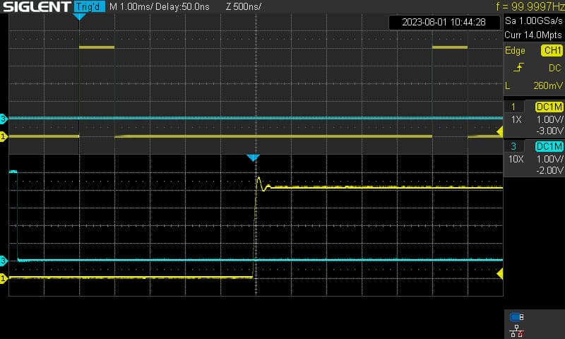
I had to use delayMicroseconds(8991), plus an extra 9 NOPs to get the correct delay.
That is the value needed by my Uno and my function generator. The actual value used will need tuning.