I have read most of the 5V relay topics I could find. I have come to the conclusion that I need a transistor and (flyback diode?) to grt thr arduino to activate the realy module. Please excuse me I have no electronics background do not understand most schematics past basic wiring . I would be very appreciative if someone could shopme how I modify my current project to use a transitor for my relay switch.
I am attaching the led to test the circuit. Eventually I want to be able to hook up 125v light and fan to control remotely.
#include <IRremote.h>

/******************************************
 *Website: www.elegoo.com
 *
 *Time:2017.12.12
 *
 ******************************************/

int relayPin1 = 4;

//int relayPin2 = 6;
int ledPin = 2;

void setup()
{
   Serial.begin(9600);

   relayPin1, (OUTPUT);
//   relayPin2, (OUTPUT);
}


void loop()
{

  Serial.println("switch Relay 1");

digitalWrite(relayPin1, HIGH); // turn the relay on (HIGH is the voltage level)
 Serial.println(relayPin1);
  delay(2000);              // wait for a second
  digitalWrite(relayPin1, LOW);    // turn the relay off by making the voltage LOW
   Serial.println(relayPin1);
   delay(2000);              // wait for a second
/*
  Serial.println("switch relay 2");
  digitalWrite(relayPin2, HIGH);   // turn the relay on (HIGH is the voltage level)
  delay(2000);              // wait for a second
  digitalWrite(relayPin2, LOW);    // turn the relay off by making the voltage LOW
  delay(2000);              // wait for a secon
*/
}
/******************************************
  Website: www.elegoo.com

  Time:2017.12.12

 ******************************************/
#include <IRremote.h>
const byte relayPin1 = 4;
//int relayPin2 = 6;
const byte ledPin = 2;

void setup()
{
  Serial.begin(9600);

  pinMode ( relayPin1, OUTPUT);
  //   relayPin2, (OUTPUT);
}


void loop()
{
  Serial.println("switch Relay 1");
  digitalWrite(relayPin1, HIGH); // turn the relay on (HIGH is the voltage level)
  Serial.println( "Relay1 : ON ");
  delay(2000);              // wait for a second
  digitalWrite(relayPin1, LOW);    // turn the relay off by making the voltage LOW
  Serial.println("Relay1 : OFF ");
  delay(2000);              // wait for a second
  /*
    Serial.println("switch relay 2");
    digitalWrite(relayPin2, HIGH);   // turn the relay on (HIGH is the voltage level)
    delay(2000);              // wait for a second
    digitalWrite(relayPin2, LOW);    // turn the relay off by making the voltage LOW
    delay(2000);              // wait for a secon
  */
}
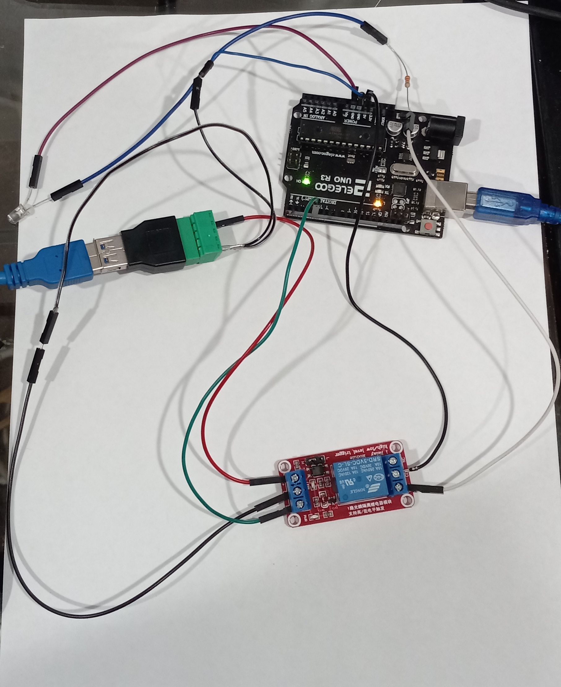
You have a relay 'module' which probably has the diode ( i can't see from the pic) , as @LarryD pointed out the resistor should be 220 Ohms.
The posted wiring diagram is OK . Try the modified sketch above to test what you have .
To operate a bare relay, you do but that is exactly why you use a relay module which is correctly designed to incorporate these.
You have apparently been reading warnings about using a separate power supply for the relay module. This is true to some extent but the relay module can probably be powered - like the LED you are using for the moment (but I suspect you intend to control something different later) from the "5V" pin given that you are powering the UNO from USB and using only one relay module. It would be best to connect a 220 µF or larger capacitor across the "+" and "GND" terminals of the relay module (noting correct polarity).
Full marks for posting code properly, you need to use "Auto Format" (Control-T) on the code in your IDE to make it read neatly.
The problem is that I am getting 1.12v from the input pin. Tried various other pins the same result. I tried two Elegoo Uno's. A nano (old bootloader) all with the same result.
How can I boost the voltage to the input?
#include <IRremote.h>

/******************************************
  Website: www.elegoo.com

  Time:2017.12.12

 ******************************************/

const byte relayPin1 = 12;
const byte ledPin = 2;

void setup()
{
  Serial.begin(9600);

}
void loop()
{
  Serial.println("switch Relay 1");
  digitalWrite(relayPin1, HIGH); // turn the relay on (HIGH is the voltage level)
  delay(2000);              // wait for a second
  digitalWrite(relayPin1, LOW);    // turn the relay off by making the voltage LOW
  delay(2000);              // wait for a second

}
I inadverdently took out the pinmode line from the script I originally posted. I put it back in and now it works. I have no Idea why it was not orignally.