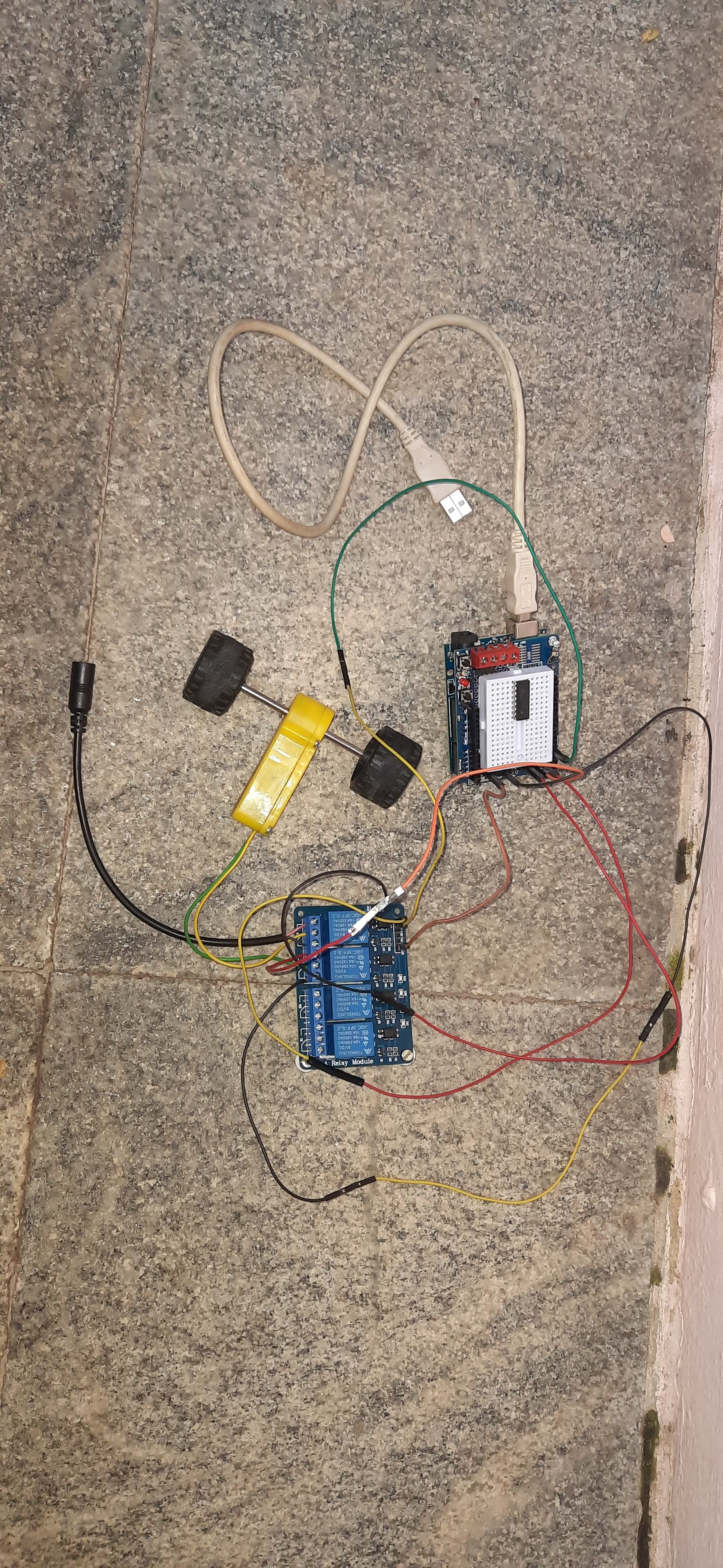
I am using breadboard shield for easier connection during prototyping only
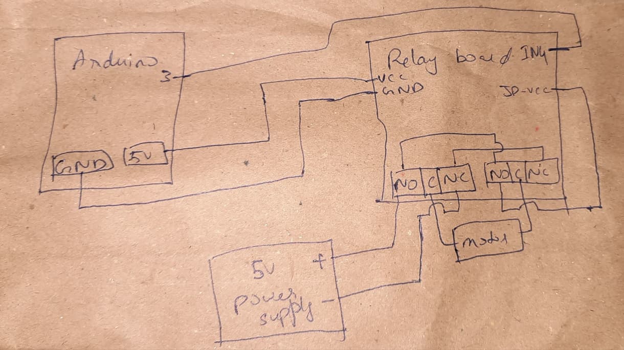
Black DC female jack is the power supply to which I connect 5V power source. I have connected black wire to NC and red wire to NO.
I have connected motor to comm of both relays
In the back side of the board, I have soldered NO to NO and NC to NC
Sorry, my bad. It is 5. I checked by connecting it to 5 again. The red light in the relay board turns off after a fraction of second and I can hear more one tick from the relay.
There are a lot of possible reasons that could cause the behaviour that you observed.
To narrow down the possible reasons to find the real reasons a lot of things must be checked.
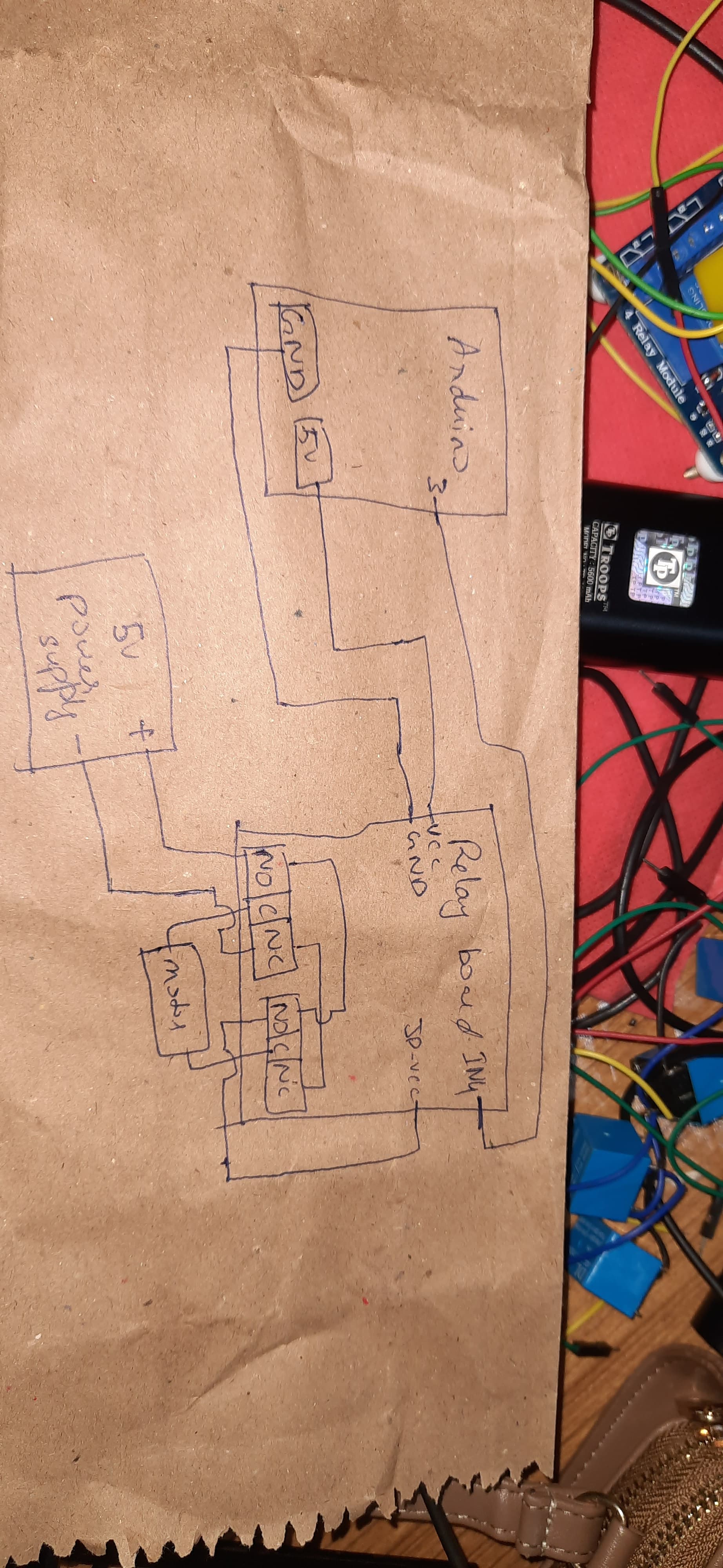
Polarity of your external powersupply.
If you have a digital multimeter you should check the polarity of your external powersupply.
Did you really connect Plus to plus and ground to ground.
I will write a pure textbased description. If you understand everything very good. If not you make the experience textbased descriptions have their limits.
If you measure polarity directly on the plug.
More often ground is outside.
next test
if you switch your digital multimeter to test conductivity (beeping if there is conductance)
if you connect one probe of the DMM with the outer contact of the power-supply-socket and the other probe with ground on your relay-board does it beep? = there is conductance ?
Or
does it beep if you connect to motor-vcc?
There must be done more tests to get a detailed picture of what are the facts. But I don't have more time at the moment
It seems that very young people have no idea how to post an image in the right aspect ratio. The way you posted it will either give me a pain in the neck when viewing on a laptop, or leave you fighting with the auto position corrector on a tablet.
Please there is more to life than portrait mode, like getting it the way you need to view it.