I am working on a project where I’m using an ATtiny85 powered by a 3.7V 700mAh Lithium Polymer (LiPo) battery. I will also include in the PCB a TP4056 battery charger to recharge the battery. I would like to implement a battery level indicator in the setup. Any suggestions or ideas would be greatly appreciated.
Have a look at this…. up to ten LEDs
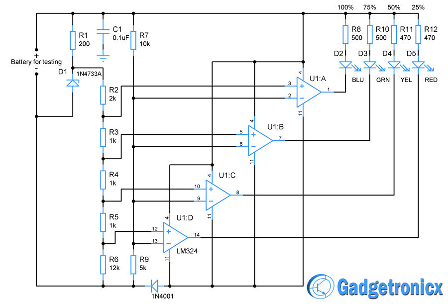
LM3914 bar graph driver.
Really simple, link outputs for fewer LEDs,
During the first 10% of the discharge cycle the battery voltage will be > 3.7V
During the next 80% of the discharge cycle the battery will be approximately 3.7V
During the last 10% of the discharge cycle the battery voltage will be < 3.7V.
So unless you have a very accurate way to measure the voltage, you can only determine if it's >90% charged, <10% charged or somewhere in between.
Well, you don't want the battery charge level display to require more time, effort, money and parts than the rest of your project. Perhaps you could give us more information about your project, such as how the ATTiny85 will be powered (directly from the battery or through a regulator), and whether your project already includes a display of some kind.
If I were in your situation, I would have the Attiny85 calculate the voltage level of the lipo via it's 1.1V internal reference
void setup() {
  Serial.begin(9600);// prints on PB0 as TX
}

void loop() {
  Serial.println(analogReadVCC());// Prints VCC in milliVolts
  delay(500);
}

uint16_t analogReadVCC(){
  ADMUX = _BV(MUX3) | _BV(MUX2); // select 1.1V Vref
  delay(1); // Wait for Vref to settle
  ADCSRA |= _BV(ADSC); // Start conversion
  while (bit_is_set(ADCSRA,ADSC)); // measuring
  return 1126400L / ADC;
}
Then you can implement whatever you want to indicate that the voltage has gone below a certain level. e.g. blink a led or enter deep sleep mode to protect your lipo.
He can do that if the ATTiny85 is being powered directly from the battery, so Vcc is equal to the battery voltage. It's a great solution because it requires no additional parts, or even using up a pin. But it won't work if he's using a regulator. The 85 should work fine at any voltage produced by a LIPO or its charger. But other parts of the circuit - sensors and such - may need a regulated voltage.
But that's not what @hmeijdam was suggesting. His code measures the 1.1V bandgap voltage with respect to Vcc. So Vcc is the analog reference, and Vbg is the input. The higher the ADC reading, the lower the battery voltage is.
Your solution makes Vbg the reference and the voltage on the GPIO pin the input. That requires the divider resistors and using up a pin. His solution requires neither. But it requires a direct connection from the battery to the 85's Vcc pin so Vcc is always the same as the battery voltage, and not a fixed 5V or 3.3V.
Not all Atmel chips have the option to select Vbg as the input. But the Attiny85 and the Atmega328P do.
That's not my experience. Perhaps you are thinking of another chemistry.
Lipos are different. This graph I googled up matches my experience:
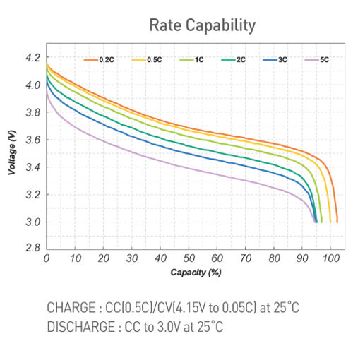
The SOC of a Lipo cell can be related to the terminal voltage throughout the discharge period.
I like the LM3914 idea, one would probably want to figure out how to measure with an expanded scale say 4.2 to 3.0 volts. Or to whatever lower limit you want to run your cells.
a7
Thank you All for your feedback. In my case Attiny85 is connected directly to the battery (no regulator). I think the solution to use the Attiny85 to calculate the voltage level will solve my issue. I will use an RGB LED to show the calculated level.
To save battery power, I would encourage you to use a blinking LED to indicate the charge level. You could flash the LED every 10 seconds or so, with four rapid flashes being fully charged, and one flash being very low. You may be surprised at how brief an LED flash can be and still be visible. Anyway, in the end, instead of having an LED on all the time, it could be on 1/100th of the time on average, or even less. Or you could have it flash only in response to pushing a button, but that would take an extra pin for the button.
I forgot about the additional power that will be used by the LED. Your idea is perfect. Also, I will use a normal LED instead of RGB LED as it consumes less power.