I'm having trouble trying to figure out how to make my LCD and my double blink program work at the same time. In my code the LCD displays the blink speed, which is controlled by the potentiometer, and holding the button makes both LEDs blink. The problem here is if I am holding the button and turning the potentiometer, this makes the LCD jutter. Does anybody know how to fix this?
Here is the code
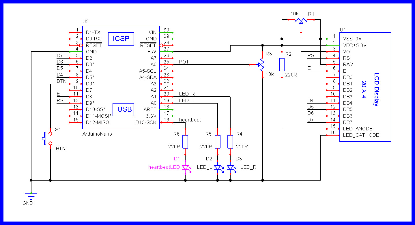
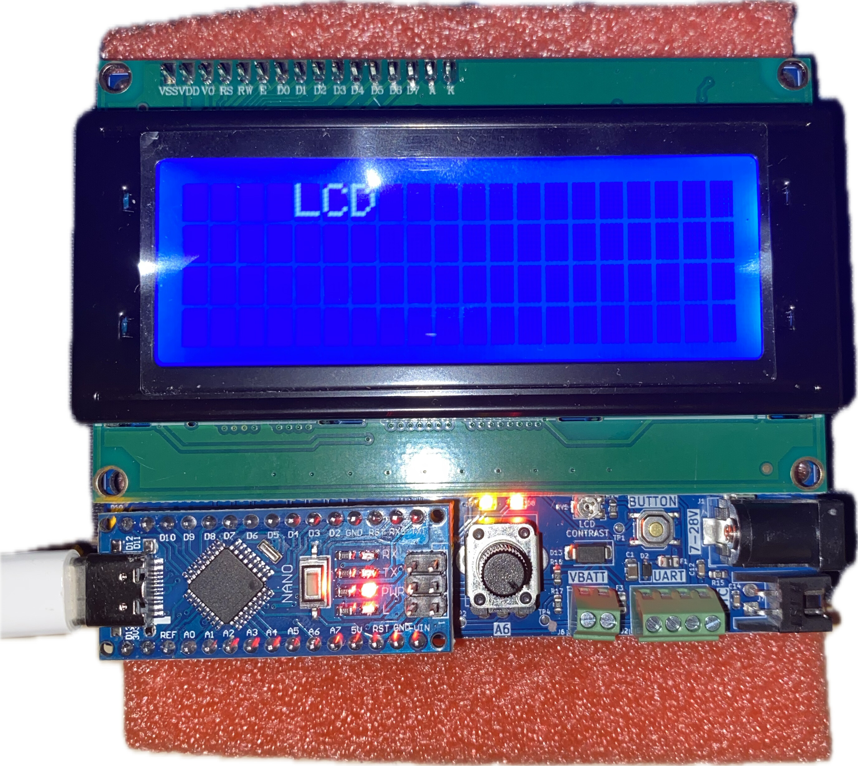
// This code is for Arduino Nano with motherboard, lcd, button, and potentiometer. Change pin values if needed.

  // MAIN
#define LED_L A0
#define LED_R A1
#define BTN 6
  // LCD
#define LCD_RS 9
#define LCD_E 8
#define LCD_D4 5
#define LCD_D5 4
#define LCD_D6 3
#define LCD_D7 2
#define LCD_BACKLIGHT 7
#define LCD_WIDTH 20
#define LCD_HEIGHT 4
#include <LiquidCrystal.h>

LiquidCrystal lcd(LCD_RS, LCD_E, LCD_D4, LCD_D5, LCD_D6, LCD_D7);

void setup() {
   pinMode(LED_L, OUTPUT);
  pinMode(LED_R, OUTPUT);
  pinMode(BTN, INPUT);
  pinMode(LCD_BACKLIGHT, OUTPUT);
    digitalWrite(LCD_BACKLIGHT, HIGH);
      lcd.begin(LCD_WIDTH, LCD_HEIGHT);
}

void loop() {
  int buttonState = digitalRead(BTN);   // Read the button state.
  int blinkSpeed = ((1023 - (analogRead(A6))) / 2 + 100);   // Read the potentiometer.

    if (buttonState == HIGH) {
      digitalWrite(LED_L, HIGH);
      digitalWrite(LED_R, LOW);
        delay(blinkSpeed);
      digitalWrite(LED_L, LOW);
      digitalWrite(LED_R, HIGH);
        delay(blinkSpeed);
  }
    else {
      digitalWrite(LED_L, LOW);
      digitalWrite(LED_R, LOW);
        delay(10);    // This is the LCD refresh rate while the lights are not flashing, when the button is pressed the light delay handles the refresh rate.
  }
    lcd.clear();    // Clears the LCD screen.
      lcd.setCursor(4, 0);
        lcd.print("Blink Speed");
      lcd.setCursor(8, 2);
        lcd.print(711 - blinkSpeed);
  }
Study the "BlinkWithoutDelay" example from the IDE.
That teaches you how to replace the blocking delay() calls with millis() timing.
lcd.print("Blink Speed"); is static text, and should be in setup().
So you don't have to wait for it to be printed every loop().
Don' use lcd.clear() in loop(). Just print the speed value where you want it.
First print blank spaces there, in case the next value has fewer digits.
Leo..
Thank you to everybody for your help. I have revised the code to use the Millis() function, but I am getting the error: "Compilation error: 'currentMillis' was not declared in this scope". I do know what this means, but I do not know where currentMillis should be declared.
// This code is for Arduino Nano with motherboard, lcd, button, and potentiometer. Change pin values if needed.

// MAIN
#define LED_L A0
#define LED_R A1
#define BTN 6
// VAR
unsigned long previousMillis = 0;
int ledState = LOW;
// LCD
#define LCD_RS 9
#define LCD_E 8
#define LCD_D4 5
#define LCD_D5 4
#define LCD_D6 3
#define LCD_D7 2
#define LCD_BACKLIGHT 7
#define LCD_WIDTH 20
#define LCD_HEIGHT 4
#include <LiquidCrystal.h>

LiquidCrystal lcd(LCD_RS, LCD_E, LCD_D4, LCD_D5, LCD_D6, LCD_D7);

void setup() {
  pinMode(LED_L, OUTPUT);
  pinMode(LED_R, OUTPUT);
  pinMode(BTN, INPUT_PULLUP);
  pinMode(LCD_BACKLIGHT, OUTPUT);
  digitalWrite(LCD_BACKLIGHT, HIGH);
  lcd.begin(LCD_WIDTH, LCD_HEIGHT);
  lcd.clear();    // Clears the LCD screen.
  lcd.setCursor(4, 0);
  lcd.print("Blink Speed");
}

void loop() {
  int buttonState = digitalRead(BTN);   // Read the button state.
  unsigned long blinkSpeed = ((1023 - (analogRead(A6))) / 2 + 100);   // Read the potentiometer.
  if (buttonState == HIGH) {
   if (currentMillis - previousMillis >= interval) {
    previousMillis = currentMillis;

    if (LED_L == HIGH) {
      digitalWrite(LED_L, LOW);
      digitalWrite(LED_R, HIGH);
    } else {
      digitalWrite(LED_L, HIGH);
      digitalWrite(LED_R, LOW);
    }
  }
  else {
    digitalWrite(LED_L, LOW);
    digitalWrite(LED_R, LOW);
    delay(100);    // This is the LCD refresh rate while the lights are not flashing, when the button is pressed the light delay handles the refresh rate.
  }
  lcd.setCursor(8, 2);
  lcd.print(711 - blinkSpeed);
}
Thank you @LarryD, this has solved my original problem but a new one has emerged. When holding the button to flash the LEDs, LED_L shows a solid light and LED_R does nothing. Do you know how I could fix this? Here is the current code:
// This code is for Arduino Nano with motherboard, lcd, button, and potentiometer. Change pin values if needed.

// MAIN
#define LED_L A0
#define LED_R A1
#define BTN 6
// VAR
unsigned long previousMillis = 0;
unsigned long currentMillis;
int ledState = LOW;
// LCD
#define LCD_RS 9
#define LCD_E 8
#define LCD_D4 5
#define LCD_D5 4
#define LCD_D6 3
#define LCD_D7 2
#define LCD_BACKLIGHT 7
#define LCD_WIDTH 20
#define LCD_HEIGHT 4
#include <LiquidCrystal.h>

LiquidCrystal lcd(LCD_RS, LCD_E, LCD_D4, LCD_D5, LCD_D6, LCD_D7);

void setup() {
  pinMode(LED_L, OUTPUT);
  pinMode(LED_R, OUTPUT);
  pinMode(BTN, INPUT_PULLUP);
  pinMode(LCD_BACKLIGHT, OUTPUT);
  digitalWrite(LCD_BACKLIGHT, HIGH);
  lcd.begin(LCD_WIDTH, LCD_HEIGHT);
  lcd.clear();    // Clears the LCD screen.
  lcd.setCursor(4, 0);
  lcd.print("Blink Speed");
}

void loop() {
  int buttonState = digitalRead(BTN);   // Read the button state.
  unsigned long blinkSpeed = ((1023 - (analogRead(A6))) / 2 + 100);   // Read the potentiometer.
  currentMillis  = millis();
  if (buttonState == HIGH) {
   if (currentMillis - previousMillis >= blinkSpeed) {
    // save the last time you blinked the LED
    previousMillis = currentMillis;

    // if the LED is off turn it on and vice-versa:
    if (LED_L == HIGH) {
      digitalWrite(LED_L, LOW);
      digitalWrite(LED_R, HIGH);
    } else {
      digitalWrite(LED_L, HIGH);
      digitalWrite(LED_R, LOW);
    }
  }
  }
  else {
    digitalWrite(LED_L, LOW);
    digitalWrite(LED_R, LOW);
    delay(100);    // This is the LCD refresh rate while the lights are not flashing, when the button is pressed the light delay handles the refresh rate.
  }
  lcd.setCursor(8, 2);
  lcd.print(711 - blinkSpeed);
}
This probably does not do everything necessary, however, it should stir some thinking within.
Remember, if you do not ask questions on the things you do not understand, you will not learn anything.
Click for Code
//This code is for Arduino Nano with motherboard, lcd, button, and potentiometer.
//Change pin values if needed.

#define LEDon                  HIGH   //PIN---[220R]---A[LED]K---GND
#define LEDoff                 LOW

#define PRESSED                LOW    //+5V---[Internal 50k]---PIN---[Switch]---GND
#define RELEASED               HIGH

#define ENABLED                true
#define DISABLED               false

#define BTN                    6
#define heartbeatLED           13

#define LED_L                  A0
#define LED_R                  A1
#define POT                    A6
//#define POT                    A2

//================================================
bool toggleFlag              = DISABLED;

byte ledState                = LOW;
byte lastBTN;

unsigned long blinkSpeed;

//Timing stuff
unsigned long previousMillis;
unsigned long currentMillis;
unsigned long heartbeatTime;
unsigned long displayTime;
unsigned long checkSwitchTime;
unsigned long toggleTime;

//LCD
#define LCD_RS                 9
#define LCD_E                  8
#define LCD_D4                 5
#define LCD_D5                 4
#define LCD_D6                 3
#define LCD_D7                 2

#define LCD_BACKLIGHT          7
#define LCD_WIDTH              20
#define LCD_HEIGHT             4

//uncomment the next line if you have a serial LCD                                <-------<<<<<
//#define i2cLCDisBeingUsed

#ifdef  i2cLCDisBeingUsed

#include <Wire.h>

//Use I2C library:     https://github.com/duinoWitchery/hd44780
//LCD Reference:       https://www.arduino.cc/en/Reference/LiquidCrystal

#include <hd44780.h>   //main hd44780 header

//NOTE:
//hd44780_I2Cexp control LCD using I2C I/O expander backpack (PCF8574 or MCP23008)
//hd44780_I2Clcd control LCD with native I2C interface (PCF2116, PCF2119x, etc...)

#include <hd44780ioClass/hd44780_I2Cexp.h> //I2C expander i/o class header

//If you do not know what your I2C address is, first run the "I2C_Scanner" sketch
//OR
//run the "I2CexpDiag" sketch that comes with the hd44780 library
//hd44780_I2Cexp lcd(0x3F);

hd44780_I2Cexp lcd(0x27);

#else

#include <LiquidCrystal.h

LiquidCrystal lcd(LCD_RS, LCD_E, LCD_D4, LCD_D5, LCD_D6, LCD_D7);

#endif


//================================================^================================================
void setup()
{
  pinMode(BTN, INPUT_PULLUP);

  pinMode(heartbeatLED, OUTPUT);

  pinMode(LED_L, OUTPUT);
  pinMode(LED_R, OUTPUT);

  pinMode(LCD_BACKLIGHT, OUTPUT);
  digitalWrite(LCD_BACKLIGHT, HIGH);

  lcd.begin(LCD_WIDTH, LCD_HEIGHT);
  lcd.clear();

} //END of   setup()


//================================================^================================================
void loop()
{
  //========================================================================  T I M E R  heartbeatLED
  //is it time to toggle the heartbeat LED ?
  if (millis() - heartbeatTime >= 500ul)
  {
    //restart this TIMER
    heartbeatTime = millis();

    //toggle the heartbeat LED
    digitalWrite(heartbeatLED, digitalRead(heartbeatLED) == HIGH ? LOW : HIGH);
  }

  //========================================================================  T I M E R  check switches
  //is it time to scan our switches ?
  if (millis() - checkSwitchTime >= 50ul)
  {
    //restart this TIMER
    checkSwitchTime = millis();

    checkSwitches();
  }

  //========================================================================  T I M E R  toggle LEDs
  //if enabled, is it time to toggle the LEDs ?
  if (toggleFlag == ENABLED && millis() - toggleTime >= blinkSpeed)
  {
    //restart this TIMER
    toggleTime = millis();

    //toggle the LED_L and LED_R LEDs
    digitalWrite(LED_L, digitalRead(LED_L) == HIGH ? LOW : HIGH);
    digitalWrite(LED_R, !digitalRead(LED_L));
  }

  //========================================================================  T I M E R  display
  //is it time to update the display ?
  if (millis() - displayTime >= 250ul)
  {
    //restart this TIMER
    displayTime = millis();

    //read the poteniometer
    blinkSpeed = (1023 - (analogRead(POT))) / 2 + 100;

    lcd.setCursor(4, 0);
    lcd.print("Blink Speed");

    lcd.setCursor(8, 2);
    lcd.print(711 - blinkSpeed);
  }


  //================================================
  //other non blocking code goes here
  //================================================


} //END of   loop()


//                                   c h e c k S w i t c h e s ( )
//================================================^================================================
//we are looking for a "change in state" on our switches
void checkSwitches()
{
  byte state;

  //========================================================================  BTN
  state = digitalRead(BTN);

  //================================================
  //has this switch changed state ?
  if (lastBTN != state)
  {
    //update to the new state
    lastBTN = state;

    //========================
    //has the switch been pressed ?
    if (state == PRESSED)
    {
      //reset the toggle TIMER
      toggleTime = millis();

      //start the toggle TIMER
      toggleFlag = ENABLED;
    }

    //========================
    //has the switch been released (opened) ?
    else if (state == RELEASED)
    {
      //stop the toggle TIMER
      toggleFlag = DISABLED;

      digitalWrite(LED_L, LOW);
      digitalWrite(LED_R, LOW);
    }

  } //END of this switch

  //========================================================================  nextSwitch

} //END of   checkSwitches()
Thanks @LarryD for that! This helped alot, but when pressing the button, the LEDs flash indefinitley, even once the button is released. I was also wondering what the purpose of having seperate variables for pressed and released switches and on or off LEDs, would it not be easier to use HIGH and LOW? Please enlighten me.
Hi @LarryD, Unfortunately I could not find ANY information about the PCB anywhere online. The board was sourced through a program called Evolocity and I think it is a custom board.
No, that is not the problem. To make to vastly different operations run in unison, they both must start and end at the same time. Does your code attempt to make both functions take the same amount of time?